Automotive exterior ultrasonic welding works consistently when the joint receives enough controlled energy while the fixture prevents the surrounding component from moving or being marked. For bumper brackets, grilles and exterior trim, that means reviewing the material, local joint geometry, sonotrode access and support beneath the welding area together. Increasing generator power or clamping a flexible part more firmly will not, by itself, correct a poor load path or an unsuitable interface.
The practical starting point is the ultrasonic welding fixture. A well-considered nest locates the exterior component, supports the relevant joining regions and allows the brackets to seat before energy is applied. Its contact surfaces must also respect the appearance requirement of the painted, textured or glossy side. These conditions have to remain repeatable after loading, routine cleaning, tooling changes and maintenance.
This guide focuses on fixture and process decisions for automotive exterior ultrasonic welding. It uses bumper bracket ultrasonic welding as the main example and extends the review to grilles, spoilers, wheel-arch trim and decorative carriers. The inspection actions are an engineering framework, not a universal machine specification. Approve the actual material grades, tooling geometry and acceptance methods through representative trials before committing a production configuration.
A successful exterior plastic welding process has several product requirements that need separate evidence. The bracket must remain attached, its functional position must be correct and the customer-facing surface must meet the agreed appearance standard. An assembly can satisfy one requirement while failing another. A strong sensor holder in the wrong orientation can create an assembly problem, while an attractive painted surface does not establish that the hidden joint has adequate retention.
For bumper bracket ultrasonic welding, begin by identifying what the bracket does. A parking sensor holder, reinforcement, guide and decorative carrier do not necessarily have the same loading or dimensional requirements. Give each attachment an identifier and record the component pair, intended process and applicable test. Include the direction in which the joint will be loaded during inspection. This makes the joining map useful to process engineering and quality teams as well as to the machine designer.
Separate local attachment from any continuous sealing function. Ultrasonic spot welding at several locations does not automatically create a sealed perimeter around a component. Similarly, a staked post can provide mechanical retention without producing a molecular bond between the retained materials. For a sensor-focused application, the Dizo Sonics bumper PDC bracket welding guide provides a related starting point. This article concentrates on how the fixture and operating sequence support the required result.
Automotive exterior ultrasonic welding should be assessed using the exact production materials. Record the resin manufacturer, grade, filler or reinforcement, color and relevant conditioning information for the exterior component and its attachment. The label PP alone does not identify the complete material system. Two molded components can belong to the same broad polymer family and still differ in stiffness, additives or behavior during joining. Keep the approved material information with the joint and tooling records.
Material suppliers develop bumper compounds around a balance of properties, rather than a single welding parameter. The Borealis bumper front fascia material overview illustrates that broader material context. It is a useful route to grade information, not proof that a selected bumper and bracket combination is weldable. Obtain the relevant technical data sheets and use production-intent molded samples to determine whether the proposed joint and ultrasonic welding fixture are suitable.
For a fused plastic joint, material compatibility also needs review. Herrmann Ultraschall explains material considerations for ultrasonic welding, including the different behavior of thermoplastic materials. Apply such guidance at the feasibility stage. Do not approve a dissimilar-material combination from a generic compatibility table alone. The local geometry, energy path and physical test results remain part of the decision for exterior plastic welding.
Record recycled content and the permitted source or grade changes when they apply. A previous recipe for a virgin compound is not automatically the release recipe for a recycled formulation. The existing recycled PP bumper ultrasonic welding guide covers that subject in more detail. For fixture development, identify which material variations were present in the samples and retain any untested conditions as explicit validation work.
The term automotive exterior ultrasonic welding can describe different local operations. A designed interface can be melted to join compatible plastics, a piercing spot-welding tool can create a localized attachment, or a plastic post can be reformed to retain a second component. These mechanisms require different contact features and acceptance checks. Label the proposed process at every location instead of referring to all features as identical weld points.
The Sonics and Materials bulletin on ultrasonic staking and spot welding explains the distinction between post retention and localized spot joining. Use the principles to frame the design review, without copying a standard tip dimension or penetration depth into an unrelated bumper application. A slender piercing sonotrode must be evaluated with the actual overlapping parts and support condition. Its motion and ultrasonic vibration do not make it a rotating drill.
Ask the application engineer to show how the joint forms and where the displaced material can go. Check for interference with a sensor, mating part or nearby clip. If a welded region must remain within a controlled envelope, put that condition on the drawing or inspection plan. Bumper bracket ultrasonic welding should satisfy the functional geometry after the horn retracts and the assembly is released, not only while the fixture is holding the components together.
An ultrasonic welding fixture must do more than hold the overall bumper outline. Review the reaction path beneath each joining location. If the horn presses on a bracket while the bumper skin can bend away, the tool movement includes component deflection as well as joint formation. The effect can vary as molded-part shape changes. Ask where the force is reacted and whether the support remains effective with the real component seated in the nest.
Herrmann Ultraschall describes fixtures as the counter-bearing for sonotrode force. That basic role is especially relevant to a large, flexible exterior assembly. Develop the support concept around the local joining areas and the approved part datums. A visually complete contoured tool can still have an unsupported region below an important weld. Review sections through the fixture and component where the load path is difficult to understand from a general arrangement drawing.
Use representative parts to check the concept before adding more process energy. First confirm seating, then apply the planned clamping sequence, and assess the local condition using the machine builder's approved setup procedure. If an area lifts, rocks or changes position, establish whether the cause is part variation, a support mismatch or clamp interaction. A fixture change should have a stated purpose, such as stabilizing a specific location, rather than simply adding contact everywhere.
For automotive exterior ultrasonic welding, support stiffness and surface protection must be considered together. A hard local contact may provide a repeatable reaction while creating an unacceptable cosmetic risk. A compliant layer may protect a finish while changing under load. The correct arrangement depends on the part and process. Record the chosen contact material, geometry and installation condition so that later replacements reproduce the validated ultrasonic welding fixture rather than create a new setup unintentionally.
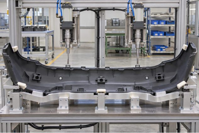
AI application illustration. Generic pneumatic ultrasonic modules with slender flat piercing sonotrodes above an exterior bumper fixture. The image is not a delivered customer machine, a dimensioned tooling drawing or evidence of production performance.
Locate the main exterior component from the agreed datum scheme, then review how each attachment is presented to it. The bumper can be correctly located while a sensor holder is tilted or only partly seated. A bracket presenter should control the relevant position without obstructing the horn or imposing an unintended gap. Define which features establish the bracket location and which features merely prevent it from moving during the cycle.
The clamping sequence can reveal a hidden problem in bumper bracket ultrasonic welding. Check the assembly before clamping, after the main clamps close and after the local bracket restraint engages. If a location changes during those steps, determine whether the fixture is seating the part or distorting it. Excessive force can conceal a mismatch until the assembly is released. Inspecting only the clamped condition can therefore give a misleading picture of the finished product.
Clearances should allow the intended process movement without losing control of the part. A bracket must remain aligned, but a restraint should not unintentionally prevent the validated joining displacement. Ask the designer to identify moving and fixed references during the weld and hold stages. Where the joint depends on a specific seating condition, consider how the station will establish that condition and which deviation it can actually detect.
When nominal parts fit but production samples do not, compare the real surfaces with the data used to manufacture the ultrasonic welding fixture. Dukane's ultrasonic welding FAQs identify tooling fit, part variation and insufficient support among relevant troubleshooting factors. Use those categories to guide investigation. They do not justify an unreviewed tool offset or a universal increase in clamp pressure. Determine the source of the difference and confirm that a proposed correction preserves the accepted datums.
Painted bumpers, textured trim and glossy grilles can react differently to handling and tooling contact. Mark the permitted support and clamp areas on the component data. Identify surfaces where rubbing, trapped debris or concentrated pressure would be unacceptable. The ultrasonic welding fixture should allow the part to be loaded and removed without sliding a critical surface across an uncontrolled edge. Review the handling path with the same attention as the stationary support.
Choose contact materials through trials that represent the intended finish and production conditions. Evaluate cleanliness, replacement method and behavior under repeated loading. A protective pad that looks satisfactory on the first sample may compress, become contaminated or change the support height with use. Define its reference condition and the inspection that indicates replacement. If the pad is part of the joining reaction path, replacing it is also a process-related maintenance action.
Protective film at the horn contact is a separate concept from padding on the nest. Dukane's discussion of buffer sheets describes a film positioned between a horn and a component in suitable applications. This should not be generalized into a recommendation to place film in a plastic fusion interface or in front of every piercing sonotrode. Its suitability depends on the contact geometry and has to be tested with the intended process.
For exterior plastic welding, distinguish protection against direct tool contact from protection against deformation transmitted through the component. A clean, soft support does not automatically prevent read-through caused by an unsuitable local process. Inspect the visible side after each development stage and connect any change to the location and operation that produced it. This gives the engineer useful evidence before changing surface-contact materials or modifying the process recipe.
The sonotrode must reach the intended feature at the correct orientation with the component fully located and clamped. Check its complete envelope, including the converter, booster, mount and nearby connections. A slender working end can reach a narrow bracket tab while the larger acoustic assembly interferes elsewhere. Review the approach and retraction paths, not only the final tool position. Maintenance access and the space needed to remove the horn also belong in the layout.
Herrmann's sonotrode overview describes application-specific ultrasonic tools and the importance of their vibration behavior. For a practical design review, ask the supplier to identify the approved acoustic stack and contact geometry. Do not machine a horn to resolve an access problem without the tooling specialist reviewing the change. An apparently minor alteration can affect a component designed to vibrate in a controlled way.
For the pneumatic piercing arrangement discussed here, the working end is narrow and flat. Its appearance should be consistent with the intended joining feature rather than a drill bit, rotating spindle or broad press block. That visual distinction helps a project team discuss access, but it does not establish a tool specification. Bumper bracket ultrasonic welding still needs a validated horn profile and local material stack for each relevant joining condition.
Other ultrasonic architectures may solve a similar exterior joining task differently. For example, TELSONIC describes torsional ultrasonic bumper welding. That is a distinct technology reference. Its tool behavior and application results should not be transferred to a longitudinal piercing system or presented as Dizo Sonics performance. Compare the actual proposed process and sample evidence when a thin cosmetic surface makes the joining method particularly sensitive.
In a cylinder-driven ultrasonic module, pneumatic motion brings the acoustic tooling to the part. The ultrasonic system supplies the high-frequency mechanical vibration used in the joining operation. Specify the approach, start condition, joining mode and hold stage for the proposed application. A description that says pneumatic ultrasonic welding does not by itself define how contact is detected or which process quantities are monitored.
Air pressure is not a direct measurement of the force at every joint. It can be a controlled setup value within a validated process, but friction, mechanism design and operating conditions matter to the resulting tool force. If measured force or displacement is required, identify the sensor, its location and the recorded signal. Dukane's P220 pneumatic press information illustrates how particular trigger and position functions depend on the selected equipment configuration; it is not a description of Dizo's standard supply.
The Dizo Sonics pneumatic plastic ultrasonic welding machine is a related equipment family for discussing pneumatic actuation. A dedicated exterior cell, however, needs its own module layout and joining review. Confirm the available control functions in the project proposal. If the application needs a programmed motion profile, review the relevant servo ultrasonic welding machine concept rather than assume that changing the actuator alone resolves the joint problem.
Assess compressed-air behavior during the complete working sequence. Several cylinders moving or clamping at once can create conditions that are absent during a single-head trial. Record the required supply conditions and investigate relevant excursions during run-off. For automotive exterior ultrasonic welding, a useful control plan connects these machine conditions to the validated operating window and defines the response when the station cannot maintain the required state.
A multi-head ultrasonic welding machine can process several fixed locations in one clamped assembly. The engineering question is which locations can operate together while maintaining acceptable joint formation and component shape. Do not select simultaneous firing solely because it appears faster. Review part stability, available support, installed acoustic capacity and the interaction between neighboring operations. Each group should have a reasoned place in the sequence and a clear result status.
Start process development with the agreed local trials, then evaluate the intended grouped operation. Compare the component position and visible surface after different approved sequences. If an issue appears only when several heads operate together, preserve that observation in the investigation. Check the common fixture, clamping and supply conditions before treating each head as an isolated source of variation. The ultrasonic welding fixture may behave differently under several local loads than under one.
The Dizo Sonics automotive exterior multi-head ultrasonic welding machine is intended for exterior assemblies such as bumpers, grilles, spoilers and trim. Use the product page to identify the relevant platform, then ask for a joining map and a proposed firing plan for the actual part family. The number of heads, grouping and monitoring detail should follow that review, not a general assumption that every attachment requires identical hardware.
Make the abnormal sequence visible as well. If one group fails after other joints have been completed, the control system needs to preserve the correct assembly status. Define whether the cycle stops, finishes a controlled sequence or routes the part to a reject process. An automatic repeat should be allowed only when the affected joint and reprocessing method have been approved. This is especially important where additional energy could change the exterior appearance.
Robotic ultrasonic welding moves the end-effector between joining locations rather than placing a dedicated fixed unit at every point. That can be useful for distributed bracket positions or a part family with different joining maps. The review must include the real ultrasonic welding fixture, fully loaded components and all clamps in their operating positions. Robot reach to a nominal coordinate does not establish that the acoustic stack can approach the joint with the required orientation and support.
For a Dizo Sonics robotic ultrasonic welding workstation, request a sequence study showing the actual end-effector envelope and the local mechanism used to establish contact. Review approach directions, cable movement, retraction and maintenance positions. Identify where a tool change or fixture change would be required for another variant. The concept should explain how the part family is accommodated within the validated work envelope, rather than rely on the general flexibility of a robot.
When comparing robotic and multi-head automotive exterior ultrasonic welding, use the same complete production task. Include loading, component checks, clamping, joining, holding, result handling and unloading. A sequence with fewer fixed heads may require more travel, while a fixed array may need more dedicated adjustment and maintenance access. These are project-specific tradeoffs. Ask each concept to demonstrate acceptable product quality and the defined output task before deciding which arrangement is suitable.
The sensor opening and its holder form a functional assembly, but hole creation and bumper bracket ultrasonic welding are separate processes. Define the location, orientation and fit required between them. A repeatable weld cannot correct a hole that is outside the approved geometry, and a correct opening does not establish that its holder is attached in the required position. Check the complete sensor arrangement after the component is released from the joining fixture.
Where the project includes mechanical punching, the bumper punching and ultrasonic welding machine provides a relevant equipment route. For a laser-based concept, review the bumper laser cutting and ultrasonic welding machine. The latter combines laser cutting of openings with ultrasonic joining; it should not be described as laser welding of the sensor brackets. Keep the cutting and welding requirements distinct in the specification and acceptance plan.
Review how the component is referenced between operations. If the bumper is transferred to another station, identify the datums used to restore its position. If the processes share a fixture, assess the access and support needed for both. The existing PDC sensor hole laser cutting validation guide covers the cutting checks. Add bracket seating, weld retention and the final sensor position to evaluate the assembled condition rather than approve each operation in isolation.
Automotive exterior ultrasonic welding has to be judged against a defined appearance requirement. Identify the visible regions, finish and viewing conditions before trial work. Agree the lighting arrangement, inspection position, relevant viewing directions and the timing of inspection after joining. A barely visible surface change can be assessed differently under another reflection or at another angle. The team needs a repeatable method and agreed reference samples to make comparable decisions.
During development, inspect the part before it enters the fixture. Repeat the inspection after the relevant handling, clamping and joining stages using approved procedures. Keep photographs linked to the joining point and the operation. If a mark is present before ultrasonic energy is applied, the investigation should include seating, clamping and handling. If it appears after joining, examine the local joint, energy input and support alongside the contact surfaces. The sequence provides evidence about the origin of the change.
Define whether a delayed inspection is required by the customer method. The acceptable condition should represent the released assembly at the agreed stage, rather than only the appearance immediately after the horn retracts. Where thermal conditioning or another exposure forms part of validation, inspect the relevant appearance and geometry afterward. Do not impose an arbitrary waiting time or environmental test that is unrelated to the customer's product requirement.
For bumper bracket ultrasonic welding, strength, bracket position and Class A appearance should be evaluated on identified samples made with the same controlled process. A recipe that improves the painted surface may change joint formation, so recheck the required product functions after an adjustment. Record the final approved combination of material, tooling, sequence and settings. This gives production a defined reference instead of several different recipes that each passed a separate portion of the review.
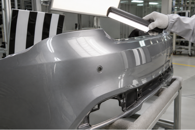
AI application illustration. A generic painted bumper appearance inspection scene. Lighting, viewing conditions and acceptance samples must be defined by the actual quality procedure; the image shows no measured result or verified pass condition.
When an automotive exterior ultrasonic welding process becomes unstable, preserve the last approved setup before making adjustments. Identify which part family, material lot, joining location and tooling condition are involved. Compare the current defect with the accepted reference. A problem that occurs at one bracket requires a different investigation from a change affecting every location. This first comparison helps the team choose a focused check instead of changing several recipes together.
Dukane's ultrasonic welder troubleshooting guidance discusses factors such as tooling condition, molded-part changes and fixture support. For an exterior production station, turn those categories into a controlled investigation. Check whether the real component still matches the approved incoming condition, whether the bracket seats, whether the supports remain clean and intact, and whether the horn returns to its established reference. Use the machine builder's service procedures when inspecting the acoustic system.
Change one identified condition, or use an agreed experimental study when several factors interact. Record the reason for the change and inspect all affected product requirements afterward. A reduction in visible marking is useful only if the bracket still meets its specified function. Likewise, a higher retention result does not justify an unacceptable surface change. The objective is to recover the approved product condition with an understood process, not merely make the current alarm disappear.
The following checks are suggested diagnostic actions. Their results guide the next investigation; none is a universal instruction to increase pressure, amplitude or welding time.
|
Observed condition |
First controlled check |
Effect on the investigation |
|
Mark exists after clamping without welding |
Inspect seating, clamp sequence and contact cleanliness |
Prioritize the fixture and handling condition |
|
Mark appears after ultrasonic joining |
Compare local support, horn contact and the approved process settings |
Investigate the joining operation and its interaction with the part |
|
One bracket has inconsistent retention |
Check its incoming geometry, seating, support and tool reference |
Focus on the affected local joining condition |
|
Several points drift together |
Compare material lots, setup, supply conditions and shared fixture elements |
Investigate common causes before retuning individual heads |
|
Bracket position changes after release |
Compare located, clamped and released geometry |
Review imposed distortion and the final functional datum |
The validation plan for automotive exterior ultrasonic welding should identify the component conditions the process is expected to accept. Include relevant material lots, mold or cavity differences and part variants within the approved incoming envelope. Do not select only the samples that fit the nest most easily. If the available samples do not represent an important condition, record that gap and the follow-up test needed before release.
Connect every trial group to its material, fixture and recipe revision. A useful record states which variable changed, which quantities were measured and which product tests were performed. Inspect the local joint and the complete released assembly. For bumper bracket ultrasonic welding, the validation should connect retention, bracket position and surface appearance rather than produce unrelated reports with no common sample identification. This makes the result easier to review when several teams are responsible for different acceptance criteria.
Use test methods that reproduce the intended failure concern. Define the bracket restraint, loading direction and acceptance criterion for a retention test. For dimensional inspection, define the datums and the released condition of the assembly. Where environmental or durability tests apply, follow the relevant customer specification and identify its revision. No strength threshold from another bumper or a supplier's demonstration should automatically become the requirement for this component.
The ultrasonic welding fixture itself needs acceptance evidence. Check its datums, local support condition, replaceable contact elements and return to reference after the agreed changeover. Review whether its sensors verify the conditions claimed in the control plan. A part-presence signal may establish that an object is present without proving correct seating at a particular weld. The validation should describe what the installed checks actually confirm and which product conditions remain dependent on inspection.
Select monitoring around the defects that matter to the assembly. Depending on the proposed controller and sensors, an ultrasonic system may provide time, energy, power or movement information. Confirm which values are measured, which are recipe settings and whether the data belong to a point, a group or the complete cycle. Automotive exterior ultrasonic welding requires this distinction when the part has many attachments and only one local joint develops a problem.
Develop acceptance windows from the validated process and the product checks. An in-window signal is evidence that the observed process quantity remained within its approved range. It does not directly measure hidden joint strength or prove that every appearance condition is acceptable. Challenge the relevant detection functions with approved sample or fault conditions and identify defects that need another check. This keeps the control plan realistic without overstating the capability of a generator display or station-level OK signal.
Define identification and recovery at the assembly level. The station should preserve the difference between a completed accepted cycle, a rejected result and an interrupted sequence with uncertain status. If records are required, include the fixture and recipe identification as well as the relevant result. Agree what happens if communication is lost or an identifier cannot be read. Data collection is useful when it helps the team trace a real condition; the required fields and interfaces belong in the project scope.
The ultrasonic welding fixture should return to its approved condition after an exchange or service action. Identify the mechanical datums, connectors, support elements and reference checks involved. A quick-change base can shorten physical handling while still requiring verification of the correct fixture and recipe. Include that verification and any first-part approval in the agreed changeover definition. Measuring only the time spent moving a tool does not describe the full interruption to production.
Prepare a maintenance plan for the items that influence exterior plastic welding quality. Inspect contact surfaces, locators, clamps, bracket presenters and the relevant acoustic tooling using the builder's instructions. Define how worn pads or replaceable supports are installed to the same reference. Keep critical spare items with the information needed to fit and approve them. An available spare is not sufficient if replacing it changes the supported height or tool alignment without a controlled check.
A handheld ultrasonic spot welding machine may be useful for approved development or localized joining tasks, but manual processing should not be treated as an automatic recovery for a failed production weld. The application, support and reprocessing method still need approval. For bumper bracket ultrasonic welding, repeated processing can affect both the attachment and the visible surface. Define the allowed repair route, or reject the part according to the agreed procedure.
Automotive exterior ultrasonic welding principles transfer across part families, but the tooling and approval do not transfer unchanged. A grille can combine a large frame, decorative surfaces and several local attachments. Its contact regions and permitted distortion may differ from those of a bumper. Review the actual load path and accessible joining features, and check whether a proposed fixed-head arrangement can support the locations without obstructing other assembly operations.
For a spoiler, distinguish bracket attachment from the shell seam and any sealing requirement. Local ultrasonic joints do not establish that the complete spoiler is watertight. The Dizo Sonics spoiler ultrasonic welding guide expands on those distinctions. Use a separate requirement for the relevant continuous joint or sealing function, then develop the ultrasonic welding fixture around the localized tasks that have been assigned to it.
Wheel-arch trim and decorative carriers can have narrow contact regions and long flexible shapes. Review how the part is supported during loading as well as during joining. Identify where a clamp could alter a visible edge or the final fit. A common machine platform may be feasible for several variants, but each must have a defined material, joint and support condition. Confirm common tooling from the relevant geometry and trials rather than from the fact that both parts are called exterior trim.
Equipment references are useful when they help the customer understand the supplied scope. The published Dizo Sonics bumper punching and ultrasonic welding project shows a related production context. When reviewing a reference, ask which operations and fixtures are relevant to the new part. Photographs can explain layout and handling, but do not establish a new program's strength, cycle time or cosmetic approval.
The published bumper laser cutting and ultrasonic welding project provides another equipment reference for combined exterior processing. Use it to discuss the division of work between cutting and joining stations, and the information needed for a new concept. Avoid assuming that a reference machine has the same material, part dimensions or inspection requirements. Automotive exterior ultrasonic welding equipment should be proposed around the current joining map and verified product requirements.
Send the complete assembly data, relevant two-dimensional drawings and an identified joining map. Include material grades, coating condition and representative component photographs. Mark the visible surfaces, locating datums and areas that tooling must avoid. If an existing ultrasonic welding fixture is being replaced or improved, add photographs of its supports, clamps and bracket presentation. The purpose is to show the actual joining and handling problem, not only the overall bumper appearance.
State the acceptance requirements in measurable terms. Include retention or strength methods, bracket position, released-part dimensions and the agreed appearance procedure. Describe the part variants, production arrangement and full cycle-time definition. Identify the data fields, plant interfaces and acceptance records needed. Where a requirement remains open, label it clearly so the supplier can separate a confirmed concept from a point requiring trials or customer input.
For a customized concept, review the relevant Dizo Sonics plastic welding solutions and request a proposal that explains the fixture and sequence. The technical response should identify the assumptions, local support concept, tooling access and evidence planned for process approval. A well-scoped bumper bracket ultrasonic welding RFQ makes it easier to compare suppliers and to discover a missing inspection or fixture requirement before machine manufacture.
The acceptable result depends on the actual material, wall geometry, finish, joint and support condition. Define the appearance requirement and test representative assemblies. A supplier's success on another part does not establish a universal no-marking guarantee for every painted bumper or glossy trim component.
A compliant contact can protect a finish, but its movement and condition under load also matter. The ultrasonic welding fixture needs adequate local reaction as well as surface protection. Approve the contact arrangement through the relevant product checks and define how its validated condition is maintained.
Insufficient energy is only one possible cause. Check material, seating, joint geometry, horn contact and fixture support before changing the recipe. Any adjustment should be followed by the required retention, position and appearance checks so that one improvement does not conceal another defect.
It may be feasible when the machine envelope, tooling access and cycle support the approved part family. Define the differences between variants and identify the fixtures, recipes and reference checks required. Common equipment does not automatically mean common tooling or a single validated process recipe.
Verify the fitted tool identity, mechanical reference, relevant connections and approved setup. Complete the first-part or restart checks required by the control plan. Include these tasks in the changeover definition so the production team knows when the station has returned to the accepted condition.
For automotive exterior ultrasonic welding, begin with the component and the required product result. Share the material system, joining map, surface condition and representative samples. For an existing bumper bracket ultrasonic welding problem, add the defect location, the current sequence and the inspection evidence. These inputs support a focused review of the ultrasonic welding fixture, the joint and the equipment configuration.
Use the Dizo Sonics contact page to request an application discussion. Ask for a concept that explains how the part will be located, supported, joined and inspected, together with any trials still required. The result should be a project-specific basis for selecting the equipment and releasing the process with clear evidence for retention, functional geometry and exterior appearance.


