A useful door panel welding machine RFQ defines the assembly, the required joints, the production conditions and the evidence needed for acceptance. It should let a supplier explain how the proposed equipment will meet those requirements and identify which assumptions still need trials. Start with those inputs before comparing head counts, robot brands or the lowest machine price. A detailed quotation is only comparable when every supplier is responding to the same part revisions, process boundaries and acceptance rules.
For automotive interior suppliers, this matters because a door trim assembly can contain several different joining tasks. A plastic bracket may require an ultrasonic weld, another component may be retained by a formed plastic post, and a decorative surface may need protection from fixture contact. Each task introduces different tooling, inspection and recovery requirements. Treating all of them as a generic welding point leaves important decisions unresolved until machine build or factory acceptance testing.
This guide explains how to turn those decisions into a practical purchasing specification. It focuses on automotive door panel ultrasonic welding, heat staking and the associated fixtures and automation. The proposed checks are an engineering planning framework. The customer and equipment supplier should agree the actual tests, limits, responsibilities and sample quantities for the specific program. No universal weld strength, cycle time or acceptance sample size applies to every door panel.
Begin the RFQ with a short description of the finished assembly and the station's responsibility. Identify the supplied components, the state in which they arrive and the state in which the finished assembly must leave. For example, state whether a map pocket is manually loaded before joining, whether speaker hardware is already fitted and whether clips are inserted by this station or elsewhere. This description gives meaning to the equipment layout and prevents a quotation from assuming that difficult assembly operations have already been completed upstream.
List the included part numbers and their current revisions. Distinguish front and rear doors, left and right variants, and any trim levels that change the bracket arrangement. A family name such as front door trim is insufficient when two versions require different joining locations or component checks. Provide a simple variant matrix showing what changes and what remains common. Ask the supplier to identify which variants are included in the base price and which require extra tooling, programming or validation.
Define the commercial boundary with the same precision. Identify who supplies production samples, test fixtures, reference components and approved appearance standards. State whether the quotation includes trial tooling, production fixtures, checking devices, training, installation and transport preparation. If a customer-owned ultrasonic generator or robot will be reused, supply its identification and available documentation. An apparently complete production cell can still leave substantial work outside the contract when these interfaces remain implicit.
Record assumptions separately from confirmed information. If the latest molded parts are unavailable, describe the revision used for the concept and the expected date of final samples. Require the quotation to explain the consequences of a later part change. This does not eliminate uncertainty, but it gives the project team a controlled way to close it. Each assumption should have an owner, the evidence needed for resolution and the decision that depends on it.
Assign a unique identifier to every required weld, stake or associated assembly feature. Place those identifiers on the same three-dimensional model views and photographs that the customer and supplier will use during design reviews. Keep the identifiers consistent in the trial report, PLC result records and acceptance checklist. A stable point map allows an engineer to connect a weak joint or a rejected cycle to the exact location without relying on descriptions such as the second weld near the speaker.
For each location, state the intended function. Is the joint carrying a specified load, locating a component, preventing rattle or retaining an insert? Identify the direction in which failure matters. Pulling a bracket away from the panel can assess a different condition from loading it in shear. Where several points work together, define whether the requirement applies to an individual feature, the complete subassembly or both. This distinction changes how a meaningful test fixture should restrain the part.
Add the local geometry and access conditions. Show the overlap, post, hole, ribs, nominal wall region and nearby visible surface. Mark any areas that the horn, heated tool or clamp must avoid. Include the operating position of moving clamps, rather than showing only an empty fixture. A horn can reach a point in an unclamped model and become inaccessible after the assembly has been restrained. Ask the supplier to review the joining map against the proposed operating sequence.
Use a controlled joining register with fields for the point identifier, component pair, process, acceptance requirement, inspection method and current approval status. Keep it concise enough to remain useful during meetings. A trial result should either confirm the proposed approach or create a defined follow-up action. If a point moves or changes process, update the register and the model together so that the machine, inspection plan and drawings continue to describe the same assembly.
Ultrasonic welding creates a joint at a suitable thermoplastic interface through localized heating produced by high-frequency mechanical vibration. Ultrasonic staking instead reforms a plastic post to retain another component. Contact heat staking uses a heated forming tool to reshape the post. These operations can appear in the same door trim assembly, but their requirements should be specified separately. A drawing that simply labels all locations ultrasonic welding can conceal the difference between a bonded interface and mechanical retention.
For an ultrasonic weld, define the component interface and the relevant product performance. For a stake, show the original post, the retained component and the required condition after forming. Clarify whether a controlled gap is permitted or whether the assembly must remain seated without movement. The retained component does not need to form a molecular bond with the post for a mechanical stake to perform its function. The test must therefore evaluate the intended retention mechanism rather than assume that all joined materials have fused.
Where a slender piercing sonotrode is proposed for a spot weld, ask for the actual tool access and penetration concept. The horn delivers ultrasonic vibration and is not a rotating drilling tool. Its contact geometry, orientation and supported material stack must be reviewed together. Do not copy a penetration depth or tip profile from an unrelated application. The supplier should confirm the proposed approach on the actual component combination and show that the visible side remains acceptable.
Limit general process descriptions in the RFQ to what is needed to make a decision. The central requirement is evidence that the chosen method satisfies the part's function. For a broader comparison before specification work, see the existing door panel welding process selection guide. The RFQ can then concentrate on the specific joints and the proof required for the proposed production station.
Supply the exact resin grade for each component, including the material supplier and the relevant technical data sheet where available. Generic descriptions such as PP, ABS or automotive plastic do not fully describe a joining application. Fillers, modifiers, colorants, moisture condition and recycled content can affect the behavior of the molded part. Record these details as inputs to the feasibility review rather than assume that two parts with the same broad polymer name will respond identically.
State how the validation samples relate to production. Identify the mold revision, cavity where relevant, manufacturing lot and any conditioning or storage requirements. If a prototype was machined, printed or molded with a different grade, disclose that difference. Such samples can be useful for checking access and handling, but they do not automatically establish a production welding window. Ask the supplier to distinguish what each trial has demonstrated from what remains dependent on production-intent molded components.
Plan sample availability around the work to be performed. Feasibility trials, fixture development, parameter studies, destructive tests and acceptance runs consume samples for different purposes. Agree quantities with the supplier after the test plan is defined. Reserve enough representative parts to investigate a problem without repeatedly changing the sample population. If the project has several variants, make sure the trial allocation covers the relevant material and geometry differences rather than only the easiest assembly.
Define what happens if the incoming parts are outside the agreed condition. A station can be designed to detect some missing or misplaced features, but it cannot be assumed to compensate for every molding deviation. Ask the supplier to document the acceptable incoming-part envelope and any limitations discovered during trials. Where uncertainty remains, keep a separate action for the molding or product engineering team instead of hiding it inside a wider welding parameter window.
The fixture specification should show where the panel is located, where joining forces are reacted and how the visible surface is protected. Request an annotated support and clamping concept before releasing the full production tool. A contoured nest alone does not explain whether the material directly beneath a joint can move or bend. The review should connect each important joining location to a practical support arrangement and identify areas where access prevents an ideal load path.
Ask how the fixture distinguishes locating from clamping. Locators establish the intended part position, while clamps maintain the necessary seating during the operation. Excessive clamp force can distort a flexible panel into a condition that disappears after release. Require the supplier to explain how the part is checked before clamping and how its geometry is assessed afterward. This encourages a fixture concept based on the accepted part condition rather than on forcing every sample into the same nest.
Specify the surfaces that may contact the tool and the approved protection approach. Soft contact material may help protect a surface, but its compression, wear and contamination must be considered. A support that changes height over time can affect both appearance and joining behavior. Request access for cleaning and replacement, and identify which contact elements need controlled reference positions. Agree how a worn protection layer will be replaced without changing the validated fixture condition.
Include maintainability in the fixture review. A technician should be able to inspect supports, replace a sensor and remove a horn without dismantling unrelated tooling unnecessarily. Ask for a service position and a defined reference method for adjustable elements. For a new fixture, require a documented check after assembly and again after installation. These checks should focus on the datums and local supports that matter to the part, rather than on an undirected list of tooling dimensions.
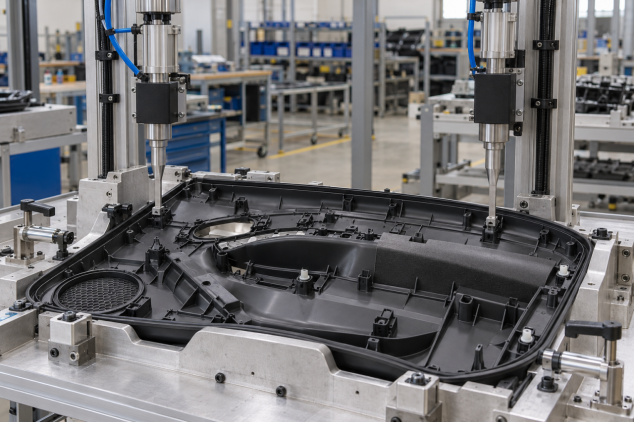
AI application illustration. Generic pneumatic ultrasonic modules with slender flat piercing sonotrodes above a supported door trim assembly. The image does not represent an installed customer machine or an approved tooling design.
For a cylinder-driven ultrasonic system, distinguish the pneumatic approach motion from the ultrasonic vibration. The cylinder moves the guided module toward the joint and establishes the required contact condition. The generator, converter, booster and sonotrode form the acoustic system that produces and transmits the vibration. Ask the supplier to identify the proposed components and explain how they suit the selected joints. A photograph of a vertical head does not provide this information.
Specify which process quantities must be controlled and which must be measured. Air pressure, cylinder position and actual tool force are different quantities. A pressure setting can be part of a validated operating recipe, but it does not by itself provide a measured force record at the sonotrode. If the application requires force data, ask which sensor provides it, where it is installed and how the signal is used. Apply the same discipline to displacement and final-position requirements.
Clarify the start condition for ultrasonic energy. Depending on the selected equipment and process, the trigger may rely on a defined position, a contact condition or a measured signal. Require the proposal to identify what is actually included and how the condition is verified. If the supplier offers several control modes, ask which one was used for the feasibility evidence. A list of optional modes should not be interpreted as proof that all are installed or suitable for this part.
Define the air-supply conditions at the machine interface and the checks required during an acceptance run. The project should address pressure stability during the working sequence, including other pneumatic functions that operate at the same time. Where several heads move together, ask how the supply and control arrangement supports consistent operation. If a pressure excursion is relevant to product quality, define its detection and the permitted recovery rather than rely on an operator noticing a gauge.
Dizo Sonics publishes a multi-head ultrasonic welding machine for automotive interior assemblies. For an RFQ, use the page to identify the relevant equipment family, then request a project-specific head layout, acoustic configuration and measurement scope. The supplied functions should be established in the technical agreement rather than inferred from general product descriptions.
For thermal riveting, identify the posts, the retained components and the required formed-head condition. Supply the relevant post and hole geometry, the component stack and any permissible movement after release. Ask the supplier to review the available plastic volume and the intended head profile before selecting the tool. A large-looking formed head does not necessarily provide the required retention if the secondary component was not seated or the post root was damaged during the operation.
Specify how the heating and forming conditions will be controlled. The proposed system should identify its temperature zones, sensor arrangement, motion control and readiness logic. Ask what a displayed temperature represents and how a relevant heating fault will be detected. A controller setpoint should not be described as a direct measurement of the polymer temperature at every post. For multiple tips, discuss how the arrangement accounts for differences between locations and how abnormal conditions become visible.
Treat cooling and release as part of the same process. Define what evidence is needed to show that the formed joint remains acceptable after the tool withdraws and the assembly is unclamped. Where parts become loose later, the investigation should consider seating, material condition and release behavior alongside temperature and dwell. Link the RFQ to the existing door panel heat staking troubleshooting guide when the project is replacing an unstable process.
For a proposed door panel servo heat staking machine, request an explanation of the servo-controlled motion and the quality information available from it. Encoder position does not automatically establish the load at every individual post. If group-level data are offered, define their limitations and the additional product checks needed. This keeps the acceptance requirements aligned with what the supplied hardware can actually observe.
A dedicated multi-head machine, a robotic ultrasonic cell and a station with several thermal tools may all be reasonable concepts for a door trim project. Compare them using the same part family and complete work sequence. A supplier should explain why the architecture suits the joining map, expected variation and required output. An equipment category is not a performance result, and a larger number of heads or robots is not a substitute for a coherent operating concept.
For a fixed multi-head layout, review access to every joint and the proposed grouping of operations. Ask which points can operate together, which require separation and how an individual failed result is identified. Include room for adjustment and maintenance in the concept review. If several locations share a generator or monitoring channel, require the proposal to explain the control arrangement. Do not assume that a single station-level result proves that every joining location was individually observed.
For a robotic ultrasonic welding workstation, request a reach and sequence study using the actual fixture and end-effector envelope. Review approach directions, tool clearance, cable routing and the local mechanism that establishes joining contact. Include loading access and maintenance positions. A robot can reach a nominal point while the complete tool cannot approach it correctly. The review should demonstrate the intended joining motion rather than only show a robot inside a fenced layout.
Where a combined station is proposed, separate its process functions in the specification. Identify the interaction between ultrasonic joining, thermal forming, component loading and inspection. Review how a fault in one function affects the part status and the rest of the sequence. Ask the supplier to explain the production consequences of taking one module out of service. This can reveal whether the proposed integration improves the actual operation or creates an avoidable dependency between unrelated tasks.
Define the event that starts the cycle-time measurement and the event that ends it. State whether the target includes manual loading, part verification, clamping, joining, holding or cooling, result handling and unloading. If a supplier quotes machine time separately from operator time, retain both definitions in the comparison. A short ultrasonic energy-on period cannot be used as the total output cycle for a station that has substantial handling or inspection work.
Request a sequence chart that identifies which activities can overlap. For an alternating-station concept, ask how the loading task and automatic operation interact. Specify the assumed operator arrangement and the component presentation method. If the concept depends on one person completing several tasks during an automatic cycle, review the actual motions and access. The acceptance run should use the agreed arrangement, including the required component checks, rather than temporarily simplifying the work to meet a timing target.
Separate normal production timing from startup, changeover and recovery. A heat staking station may have a readiness period, while a robot station may require a defined reference check after a tool change. Identify which conditions must be established before the timed run begins. Also define how routine stops will be recorded during the run. This makes a cycle-time claim easier to assess without confusing steady operation with the time needed to make a station ready.
Link the timing requirement to acceptable output. Ask for records that show the completed cycle, the part status and any interruptions. If a run produces assemblies that later fail the agreed quality checks, those results need to be considered alongside the speed evidence. Avoid accepting a faster recipe in isolation. The process used for the timing demonstration should be the same approved process used for the associated appearance, strength and functional evaluations.
Write the product requirement in terms that an inspector can apply consistently. For joint strength or retention, define the loaded feature, load direction, restraint, test speed or method where applicable, and pass criteria. For appearance, define the inspected surface and the viewing conditions. For dimensions, identify the datums and the measurement condition after release. A requirement such as no visible mark or strong weld needs an agreed interpretation before it can support a repeatable acceptance decision.
Use representative reference samples and photographs when they clarify a cosmetic limit. Record how the parts were illuminated and viewed, and identify the regions that receive the highest scrutiny. If an appearance problem can develop after the assembly cools or relaxes, define when inspection takes place. The acceptance plan should also say who resolves a borderline result. This avoids repeatedly changing the standard during supplier trials or relying on different inspectors to interpret an unwritten expectation.
Select process-monitoring limits after establishing their relationship to acceptable and unacceptable product conditions. Weld energy, time, power, displacement and thermal forming results can help detect deviations, depending on the installed equipment. They are indirect evidence of the process. An in-window result should not automatically be described as a direct strength measurement. Ask the supplier to demonstrate what the proposed limits can detect and identify important defects that still require another check.
The existing door panel ultrasonic welding validation guide provides additional context for product checks. In the RFQ, translate that context into the actual methods, acceptance authority and records for this program. Where an OEM test specification applies, identify its document number and revision and make the relevant content available through the agreed project channel.
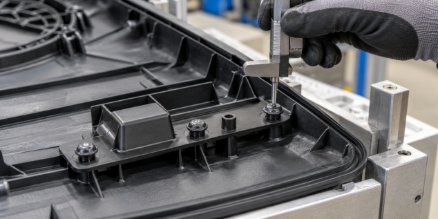
AI application illustration. A generic inspection scene around a formed plastic stake. The drawing and agreed measurement procedure must define the actual reference surface, gauge and acceptance limit; this image shows no measured result.
Specify the states in which an assembly may leave the station. A useful requirement distinguishes an accepted cycle, a rejected cycle and an incomplete cycle whose final quality status is uncertain. Ask how the operator sees the difference and how each state is recorded. A power interruption after some welds have been completed should not silently create a normal pass result when the machine restarts. The specification should describe the intended disposition of that partially processed assembly.
Define recovery for the defects the project needs to manage. Examples include a missing bracket, a failed part-identification check, an out-of-window weld result and a temperature-not-ready condition. Ask which conditions block cycle start and which can interrupt an operation already in progress. For each important fault, specify who can acknowledge it and what must be checked before production resumes. The fault list should describe the equipment's actual functions rather than promise detection of every possible assembly defect.
Treat automatic retries as a process decision. Repeating an ultrasonic cycle or reforming a previously processed stake can change the material and the appearance of the joint. If reprocessing is permitted, define the approved method and how it is validated and recorded. If it is not permitted, the control system should guide the assembly into the agreed reject route. A retry setting that makes the station easier to clear can otherwise obscure the origin of a quality problem.
Challenge the recovery logic during acceptance. Prepare approved fault scenarios using safe methods agreed with the machine builder. Verify the response, displayed instruction, stored status and release condition. For a multi-head system, include a case in which one location fails while the other operations complete. The purpose is to confirm that the station preserves the correct product status and supports a controlled response when the cycle does not follow its normal path.
Begin with the question the production team needs the data to answer. It may need to identify the recipe used, connect a rejection to a particular joint or investigate a component lot. Define the assembly identifier and the point at which it becomes associated with the machine record. If the plant uses batch identification instead of individual serialization, state that clearly. The data structure and acceptance demonstration should follow the actual traceability objective.
Specify the fields, units and level of detail. A result for the complete station, a group of heads and an individual joint are different records. Ask for a sample export showing the proposed identifiers and values. Clarify which quantities are measured, which are programmed settings and which are calculated. If a value is unavailable on the selected controller, require the supplier to identify that gap before order placement. This prevents a generic data-logging requirement from becoming an unresolved integration issue.
Define the interface boundary with the plant system. State the communication method, responsibility for mapping the fields, data-retention requirement and expected behavior if the network is unavailable. Ask whether production may continue with local records or must stop. Agree how missing or duplicate records are detected and what happens when communication returns. These are operational decisions that should be reviewed by the customer's production and information-technology teams as well as the equipment supplier.
During FAT, inspect actual records from the accepted and challenged cycles. Follow one assembly identifier from loading through the stored result and the exported data. Confirm that the recipe revision and joining identifiers match the approved documents. If an MES interface cannot be fully tested before shipment, record the remaining test and its owner for SAT. A functioning local file export can be useful evidence, but it should not be presented as a completed plant-system integration.
Start the process study with representative components and a stable trial setup. Record the part condition, tooling revision and parameters for each test group. Agree which outcomes will be measured and how the samples will be identified after testing. Without this basic discipline, a promising result can be difficult to reproduce because the team cannot determine which combination of part, fixture and recipe produced it. The study should leave a usable record for later machine development.
Investigate the process factors that are relevant to the selected joining method. For ultrasonics, this may include the validated contact condition, amplitude, termination strategy and hold stage. For heat staking, it may include the heating condition, forming motion, dwell and release. Choose the study design with the responsible process engineer. The aim is to understand the acceptable operating region and important interactions, rather than adjust several settings together until one sample looks satisfactory.
Include realistic part variation where it can affect the result. Review material lots, molding conditions, component seating and variant geometry within the approved input envelope. If only nominal samples are available, record that limitation and plan the remaining checks. A machine should not be declared tolerant of production variation solely because it processed a small group of selected parts. The validation record should show which conditions were represented and which remain to be confirmed.
Where environmental exposure, aging or durability testing is required, use the applicable customer method and evaluate the joint afterward as specified. Agree who performs those tests and how their results affect process release. Avoid selecting a convenient generic test that does not represent the product requirement. The same principle applies to statistical capability claims: define the characteristic, measurement method, sampling plan and required analysis before using a capability value as an acceptance condition.
Factory acceptance testing should use an agreed protocol that connects requirements to evidence. Prepare it before the machine is finished so that missing fixtures, samples or test methods can be addressed in time. Each item should identify the requirement, the method, the record and the acceptance decision. Separate document review from product testing and sequence demonstrations. This keeps the event focused and makes it easier to understand which open items prevent shipment and which can be closed later.
Start by confirming the physical and documented configuration. Check the supplied tooling, identified modules, approved part variants and controlled software and recipe versions. Review relevant instrument records and the equipment documentation required by the agreement. Walk through the actual production sequence with the intended component presentation. If the machine differs from the approved concept, record the change and the evidence that supports it instead of accepting the change solely because the demonstration runs.
Run the agreed production and product tests with traceable samples. Record the operating conditions, cycle information, interruptions and inspection outcomes. Include the relevant locations and variants identified by the validation plan. Where destructive tests are required, maintain a clear link between the tested joint and its process record. The quantity and duration should come from the program's acceptance plan. A video of one successful cycle can explain operation, but it does not replace the agreed run and test records.
Finish with a structured review of deviations. Distinguish a failed requirement from an observation or a document that needs correction. Assign an owner, closure evidence and the effect on shipment approval. If the customer accepts a temporary deviation, record its scope and the remaining obligation. This provides a clear basis for follow-up. It also prevents a machine from arriving at the plant with an informal list of issues that different teams remember differently.
|
Requirement area |
Evidence to request |
Decision supported |
|
Part and tooling revision |
Identified parts, fixture record and approved joining map |
The tested configuration matches the purchase scope |
|
Joint performance |
Traceable product-test records using the agreed methods |
The joints meet the specified function |
|
Appearance and geometry |
Inspection records under the agreed conditions |
The released assembly meets cosmetic and dimensional requirements |
|
Production sequence |
Timed run with the agreed loading and checks |
The complete station meets the defined output task |
|
Fault and recovery behavior |
Approved challenge records and stored part status |
Abnormal cycles receive the correct response |
|
Traceability |
Actual local and exported records |
The required assembly and process information can be retrieved |
|
Changeover |
Recorded tool and recipe change demonstration |
The station can return to the approved condition |
Site acceptance testing checks the equipment after installation in the customer's production environment. Agree what must be repeated and what evidence can be carried over from FAT. Confirm utilities, tooling installation, connections and reference positions before judging the process. If the station uses plant data systems or upstream handling, include those actual interfaces. A successful factory run does not by itself demonstrate that the installed station has the same operating conditions or complete line integration.
Use the intended operators and component supply arrangement where the acceptance plan requires them. Observe loading, checking and unloading, including routine activities such as replenishment and handling a rejected assembly. Verify that instructions and alarms are understandable to the local team. Where a translated interface or manual is included, review it in the relevant operating tasks. This helps distinguish a process problem from an installation, training or work-method issue.
If performance differs from FAT, compare the conditions before changing the approved recipe. Check the incoming samples, compressed-air behavior, fixture seating, tool references and relevant setup information. Preserve the original accepted settings and record any proposed change. An immediate parameter adjustment can make production resume while leaving the cause unexplained. A controlled comparison provides a better basis for deciding whether the machine, the installation or an upstream condition needs correction.
Define the final handover records and the responsible signatories. The package can include the accepted specification, operating and maintenance instructions, spare-parts information, program backups, inspection records and open-item closure. Agree the exact content in the contract. Training completion and a successful restart from the approved backup can be useful demonstrations when they are part of the scope. The final decision should state which requirements have been met and which obligations remain active.
For a machine serving several door panel variants, define what a changeover includes. It may require a fixture exchange, head adjustment, recipe selection, component-check changes or a combination of these actions. Agree the start and finish conditions for any changeover-time target. Include the reference checks and first-part approval needed before normal production. Timing only the physical fixture movement can leave the production team with a misleading estimate of the actual interruption.
Ask how the station prevents a mismatch between the fitted tooling, loaded part and selected program. The appropriate solution depends on the project, but the required response should be explicit. If identification is automatic, define the behavior for an unreadable or incorrect identifier. If selection is manual, describe the verification that supports it. Demonstrate the selected method during acceptance so that the project does not rely on an untested assumption about operator memory.
Request a maintenance concept for the elements that influence product quality. These can include sonotrodes, thermal tips, fixture contact surfaces, locators, clamps and the relevant sensors. Ask what condition indicates inspection or replacement and how a serviced element is returned to its reference position. Define the spare items needed for the planned operating model. A spare component is useful only when the maintenance team also has the instructions and evidence needed to install it correctly.
Set a change-control rule for modifications after process release. A new resin grade, revised bracket, repaired horn, replaced support or software change may require a documented assessment and additional checks. The required response should reflect the effect of the change. Keep the approved reference records available so that engineering can compare the revised condition with the accepted one. This makes it easier to preserve the process as the equipment and product evolve through production.
Create a comparison sheet from the requirements, not from the headings each supplier happens to use. For every important item, record whether it is included, optional, excluded or dependent on unresolved information. Review the joining map, tooling quantity, measurement functions, validation work and acceptance support in the same way. Ask each supplier to explain deviations directly. A low price can be meaningful, but only after the team understands what work and responsibility the price covers.
Look closely at features described with broad terms such as force control, traceability, quick change and automatic inspection. Ask what hardware, software and test evidence sit behind each term. A station may store a pressure setting while another measures tool force. One quotation may provide local result files while another includes a defined plant interface. These differences affect both price and acceptance, so they should remain visible in the technical comparison rather than disappear into a general compliance statement.
Evaluate the project schedule against the information it depends on. Identify the dates for final part data, representative samples, tooling approval and acceptance testing. Ask which milestones cannot be committed until those inputs are available. The delivery plan should distinguish equipment manufacture from installation and production release. This helps the purchasing team judge a proposed lead time without assuming that all product and process questions have already been resolved.
Consider the operating cost of the agreed concept alongside the purchase price. Review labor assumptions, planned consumables, quality-related maintenance, spare tooling and the work needed for additional variants. Use project-specific evidence where it is available and keep estimates labeled as estimates. Avoid applying an unsupported percentage saving from another application. A clear scope and a credible acceptance plan provide a better basis for a purchase decision than a general promise of higher efficiency.
Yes, a preliminary concept can be based on controlled part data and stated assumptions. Its limitations should remain visible. Identify which process results, tooling details and commercial commitments still depend on representative samples. Ask for a defined review when those samples become available so the preliminary quotation does not silently become a production guarantee.
The actuator type alone does not determine the available monitoring. The generator, controller, sensors and integration define which quantities can be controlled and recorded. Ask for the installed configuration and a sample result record. If a required characteristic depends on an optional sensor, include that sensor and its acceptance demonstration in the agreed scope.
That depends on the product risk and the customer's traceability requirement. Individual records can help investigate a particular location, while some systems monitor groups. Specify the required detail and ask the supplier to show how the selected architecture provides it. Any remaining blind spots need an appropriate product check or a revised monitoring concept.
It can demonstrate the agreed nominal condition if that is what the protocol covers. The acceptance report should identify the sample population and the limits of the demonstration. If approval requires evidence across variants or expected part variation, those conditions need to be represented or retained as explicit open validation work.
Some checks may be repeated, but SAT should address the installed environment and actual interfaces. Utilities, operators, component presentation and plant data connections can differ from the factory setup. Agree the relationship between the two tests before shipment and identify which requirements can only be demonstrated at the customer's site.
To begin a door panel welding machine review, send the current three-dimensional assembly data and drawings, exact component material grades, an identified joining map and photographs of the molded parts. Include the required strength, retention, appearance and dimensional tests. State the part family, production arrangement, target cycle definition, destination plant conditions and the expected FAT and SAT evidence. Identify any samples or requirements that are still pending.
If you are improving an existing station, add photographs of the fixture and tools, the current operating sequence and examples of the observed defect. Where permitted, include the associated process records and inspection method. This helps the discussion focus on the relevant interface, support or control issue. Share confidential project data through the communication channel agreed with your team and the equipment supplier.
Use the Dizo Sonics contact page to request a technical discussion and identify the intended equipment family. Ask for a proposal that separates the confirmed concept, the trials still required and the functions included in supply. An RFQ built around those decisions gives engineering, purchasing and production a common basis for selecting the station and verifying it before release.


