If a bracket moves after door panel heat staking, check the formed head, component seating, fixture support and cooling sequence before increasing temperature. A joint can appear secure while clamped and develop clearance after release. This guide covers heated-tip thermal riveting, where a molded plastic post is reshaped to retain another component. Settings and acceptance limits must be established for the actual resin, post and assembly.
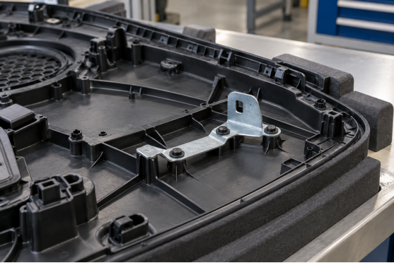
AI-generated application illustration of a heat-staked bracket on a door panel. Head geometry requires validation on actual parts.
Mark each suspect stake point and inspect the assembly at the same defined stages: before staking, after cooling in the fixture, and after unclamping. Use an agreed method to check clearance or movement. Distinguish bracket rotation, axial lift and panel flex; they do not necessarily have the same cause.
If movement appears only after release, investigate seating, panel recovery and clamp timing. If it exists before release, inspect head formation and the captured stack first. Keep the part variant, material lot and process record with each sample so comparisons remain meaningful.
Measure post diameter, wall thickness for hollow posts, and usable height above the retained component. Compare good and suspect molded parts against the drawing. A shorter post or thicker component stack can leave insufficient material to form the intended head.
Inspect head coverage around the hole, symmetry, cracks, thinning and damage from tool withdrawal. A broad head alone does not prove adequate retention. Compare the forming-tip cavity with the available plastic volume and check alignment. Use sectioned samples where necessary to examine the post root and hidden damage. Correct geometry problems before compensating with more heat or force.
Check that the bracket rests on its intended locating surfaces without interference from flash, trapped fabric, misplaced foam or an incorrect component. Verify hole position, component thickness and loading orientation. The forming tool should not be relied upon to push a poorly seated assembly into place.
Compare seating before and after clamping. A gap that closes only under clamp force may return when the panel is released. Investigate component fit and local support. Where clearance is checked with a gauge, define its location and applied load; do not force a gauge into a joint and then treat the resulting movement as an existing defect.
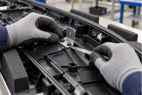
AI-generated application illustration of a seating-clearance check after cooling. The image does not establish an acceptance limit.
Confirm that supports contact the intended areas near the stake points and that the panel locates consistently. Check for worn pads, contamination and a bracket rocking in its nest. Observe whether clamping bends the panel or the secondary component.
On a multi-point heat staking machine, compare each location rather than averaging the results. If defects follow one tool position, inspect its tip, heater, sensor and alignment. If they follow one part variant, review its molded dimensions and stack-up. Establish whether local adjustment is needed before changing a recipe shared by every point.
Confirm the resin grade, filler and supplier conditioning requirements. Compare actual tool-temperature behavior, forming position, speed, dwell and cooling with the approved process. A controller setpoint alone does not establish the temperature reached throughout the plastic post.
Insufficient softening can leave an incomplete or stressed head. Excessive heating can damage the post or surrounding assembly. Examine retained samples and records before selecting a corrective trial.
Check when the tip retracts and when component clamps release. The head and assembly must remain stable through the qualified cooling sequence. Where post-cooling is used, verify air delivery and tool-temperature recovery between cycles. Excessive cooling can also disturb the next cycle, as noted in the Dukane thermal press manual. Evaluate startup, continuous running and restart conditions; do not adopt a universal cooling time.
Visual inspection should be supported by the customer-defined retention test. Agree on loading direction, test speed, support arrangement and acceptance criteria. A whole-assembly pull can conceal a weak individual stake when neighboring points carry the load.
Record the failure mode as well as peak force: head pull-through, post fracture, bracket deformation or panel damage. Separate immediate looseness from movement after specified thermal or environmental conditioning. A machine OK signal confirms only the limits it monitors; correlate those records with physical checks on released assemblies.
For a new automotive door panel heat staking machine, discuss local support, tip access, heating-zone control, forming-position monitoring, cooling and variant verification. Dizo Sonics offers servo-driven door panel systems with application-specific thermal tooling; the supplied configuration must be agreed for the project.
Choose monitoring that detects the identified failure. Position monitoring can help identify abnormal forming travel, but it cannot alone confirm that a bracket was fully seated or that the cooled joint meets retention requirements. For process selection, see the door panel welding and heat staking guide.
Provide the assembly drawing and 3D files, post and hole dimensions, material grades, component stack, stake-point map and samples of good and loose joints. Include current settings, cooling and release sequence, photos of each marked location, required retention test and target station cycle. Contact Dizo Sonics to review tooling, process suitability and sample-trial requirements for your door panel assembly.


