Automotive spoiler ultrasonic welding can be considered for designed thermoplastic joints, mounting brackets and internal supports when the material, tool access and local support are suitable. Qualify each attachment for retention strength, final position and visible surface quality. If the spoiler also needs a continuous shell seam or water barrier, define and validate that requirement separately from its local bracket welds.
For Tier 1 suppliers and OEM engineers, a rear spoiler combines a visible exterior surface with hidden attachment features. A bracket that passes a simple pull test can still leave an unacceptable mark or hold the spoiler in the wrong position. Joining development therefore needs the finished assembly, its coating condition and its mounting requirements.
Our robotic ultrasonic welding workstation supports spoiler and other automotive plastic joining applications. This guide focuses on the engineering checks that should precede station selection and production release.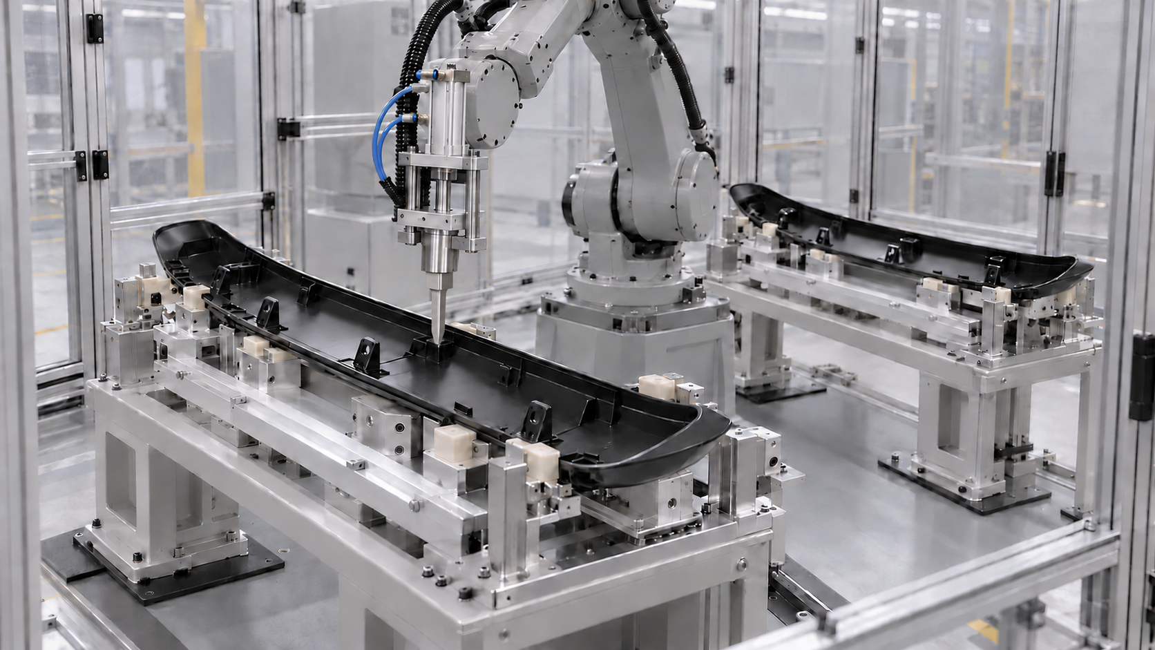
Mark every joining location on the spoiler CAD model. Identify whether it is a fusion weld between compatible thermoplastics, a formed plastic stake, or a different attachment. Herrmann explains ultrasonic joint types and staking. Staking retains another component by reforming a plastic post; it does not require the retained component to fuse with the post.
Local bracket welds and a continuous upper-to-lower shell seam serve different functions. For a long seam, assess joint accessibility, clamping, permitted component motion and any sealing requirement before choosing the process. TWI compares thermoplastic welding methods. A vibration friction plastic welding machine is one option to evaluate where the joint and part can accommodate the required relative motion; suitability for the specific spoiler must be demonstrated.
Record the intended function of each joint. Retaining a bracket, supporting a shell and sealing a water path require different acceptance evidence. Successful local welds alone do not establish the performance of the complete spoiler assembly.
Document the exact grades of the spoiler substrate and bracket, including filler, colorant and any permitted recycled content. A polymer family name alone does not establish fusion-weld compatibility. TWI identifies factors affecting ultrasonic weldability, including polymer structure, melt flow, moisture, additives and mold-release agents.
State whether joining takes place before painting, after painting or between coating operations. Show which surfaces contact the horn and fixture, and whether paint or another coating can enter the joint interface. Use samples in the intended production condition. A recipe developed on an unpainted sample needs review before it is applied to a painted variant.
We recommend including the approved color and coating variants in the sample plan. Keep the resin, molding and coating records with the trial results so that a later material or paint-process change can be assessed against the qualified combination.
Review the energy-directing feature, initial contact, mating fit and available weld collapse. Also check the distance and geometry between horn contact and the joining interface. TWI describes ultrasonic component and joint design, including the importance of energy transmission and supporting the molded features.
We recommend reviewing how service loads reach the bracket. A force acting away from the weld plane can create a bending moment and peel the attachment. If the part design permits, compare bracket footprints and support features that reduce this effect. Test the actual geometry in the relevant load direction instead of ranking concepts only by nominal weld area.
For example, a clip carrier loaded at the end of a projecting arm should be tested through that arm with representative constraint. Pulling directly beside the weld may load the attachment differently. Define the test grip, support, loading direction and rate so that development results can be compared.
Identify the cosmetic surface and any restricted tool-contact zones on the drawing. Inspect for scratches, gloss changes, residue, flash and local print-through. Dukane discusses cosmetic defects in plastics assembly, including ultrasonic surface marking and flash control. Any protective interface or tooling treatment must be checked with the actual part and process.
We recommend recording appearance before and after joining under the same lighting and viewing conditions. Retain approved reference samples and photograph the reverse side as well as the painted surface. This helps distinguish pre-existing molding or coating defects from changes introduced during clamping and welding.
Our automotive exterior multi-head ultrasonic welding machine uses contoured support and application-specific head positions. For a spoiler, the tooling review should confirm that the nest carries the joining loads without forcing the shell into a temporary shape. Inspect the part again after unclamping and after any specified conditioning.
A robotic ultrasonic welding cell moves the tool between distributed joints. This can suit a curved spoiler or changing attachment map when reach, local access and station cycle are acceptable. Simulate the approaches and verify them with representative tooling. Robot positional performance alone does not determine the weld result.
A fixed multi-head station can suit stable joint locations and recurring volumes. Compare individual, grouped and simultaneous firing where technically feasible. Confirm part stability and surface quality before selecting the sequence. A larger head count or a second robot needs a demonstrated benefit in the complete station cycle.
For an alternating two-station concept, verify loading time, fixture consistency and correct program selection at both stations. Include component checks, clamping, robot travel, welding, hold, unloading and recovery in the cycle study. Quote the agreed start and finish points when reporting cycle time.
TWI explains mechanical testing of plastic welds and why a test should represent expected service conditions. A convenient short-term specimen test is useful for development, but its result cannot be assumed to represent every load or environment experienced by the finished spoiler.
The following is a recommended validation matrix. The customer drawing and specification must define the actual methods, loads, exposure conditions and acceptance limits. No universal force, temperature, exposure duration or cycle-time target is proposed here.
|
Check |
Evidence to collect |
Acceptance reference |
|
Bracket retention |
Result in the relevant load direction; failure load, location and mode. |
Approved component test and required retention. |
|
Bracket position |
Coordinates and angle relative to the spoiler mounting datums after release. |
Drawing and assembly tolerance requirements. |
|
Visible surface |
Painted-side photographs and appearance inspection before and after joining. |
Cosmetic zones and customer reference samples. |
|
Vehicle fit |
Mounting engagement, gaps and alignment on the specified gauge or assembly. |
Approved installation and fit criteria. |
|
Conditioned performance |
Retention, geometry and appearance after the required environmental exposure. |
Customer exposure and retest specification. |
|
Water path if required |
Assessment of the defined seam or barrier and its specified functional test. |
Product-specific sealing requirement. |
|
Repeatability |
Results by joint, station, cavity and approved variant during the agreed run. |
Sampling and process-capability plan. |
Keep results for individual attachment locations. Report whether a failure occurs at the interface, in the bracket or in the spoiler substrate, and assess it against the required load. A changed failure mode can be informative, but a substrate failure alone does not prove that the complete assembly meets its specification.
Define the trial variables with the joining-equipment supplier. Relevant controls can include amplitude, trigger conditions, force, weld time or energy, displacement and hold conditions, depending on the controller. Dukane outlines ultrasonic setup and sample trials. Test the assembled part before moving from initial settings into production.
We recommend comparing a nominal recipe with nearby settings using both retention and appearance checks. Include the agreed range of molded-part fit and production conditions. Record the weld order because a recipe that succeeds on one isolated joint may behave differently in the complete clamped assembly.
During the factory acceptance test, challenge missing brackets, wrong variants and interrupted cycles. Verify the approved restart path and how the station handles a partially completed spoiler. Store available results by joint and station when this is included in the equipment scope. Data logging and plant-system interfaces should be specified explicitly.
It can be evaluated where the joint material, tool access and support are suitable. Qualification must use the actual coating condition and appearance criteria. Confirm whether coating enters the fusion interface and test the painted surface after release and any required conditioning.
A local bracket weld establishes an attachment. Watertightness depends on the relevant shell seam or water barrier. If sealing is required, identify that path and perform the specified functional test independently of the bracket-retention check.
Use the customer specification and the bracket load path. Define the required loading direction, test method and acceptance force before trials. Preserve those conditions when comparing samples. A single force value without its test setup is not enough to compare joints.
The complete station cycle determines the comparison. A robot requires motion between points, while fixed heads require dedicated access and support. Include handling, checks, joining and hold stages. Select the layout from the verified cycle, variant needs and maintenance access.
Send the spoiler CAD model, bracket map, resin grades, coating sequence and production samples. Include the mounting datums, appearance criteria, retention test and required station cycle. Contact Dizo Sonics to review the joining method, fixture concept and automation options for your automotive spoiler project.


