


Integrate programmable laser cutting and ultrasonic bracket welding in one production cell for front and rear automotive bumpers. Dizo Sonics designs single-robot and dual-robot systems for radar/PDC holes, parking-sensor brackets, mixed bumper variants, process control, and Class A surface protection.
Request a Technical Proposal | Send Your Bumper Drawings
Reference cycle times depend on part geometry, robot travel, hole contour, extraction delay, bracket loading, number of weld points, inspection, and plant interface requirements. Final takt time must be confirmed by simulation and sample trials.
Modern bumper programs may require different openings and brackets for parking sensors, radar modules, cameras, headlamp washers, reflectors, and market-specific option packages. A fixed punching solution can be highly efficient for one stable design, but frequent variants and engineering changes increase dedicated-tooling requirements.
The Dizo Sonics bumper laser cutting and ultrasonic welding machine combines programmable opening creation with controlled bracket joining. The cell locates and supports the bumper, executes the selected cutting recipe, manages fumes and debris, verifies the corresponding bracket, and completes ultrasonic welding under monitored parameters. The result is one coordinated process designed around the complete part rather than two disconnected machines.
Explore Dizo Sonics automotive plastic welding machines for bumpers, door panels, tanks, lamps, and interior components.
Robot programs can support different hole quantities, shapes, and positions. A new variant normally requires engineering validation, a production recipe, and the correct fixture or change parts rather than a complete new punching machine.
Laser cutting, extraction, bracket verification, ultrasonic welding, inspection signals, and production data can operate under one PLC-controlled sequence.
The bumper fixture supports the B-side and controls local movement during cutting and welding. Horn design, support geometry, amplitude, force, and energy are validated to reduce witness marks or deformation on the painted Class A surface.
Recipes, part identification, fixture interfaces, and standardized connections support planned changeover between bumper variants. Reference fixture changeover is 15-20 minutes with an electric forklift, subject to the approved layout and fixture design.
Laser cutting has no conventional punch and die edge to sharpen. Optical protection, extraction, robot calibration, focus control, and process validation remain essential maintenance items.
Choose one robot for moderate takt-time requirements or two robots for higher output, more holes, complex travel paths, or parallel processing.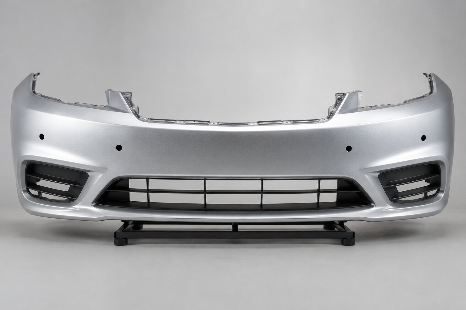
4 Radar Holes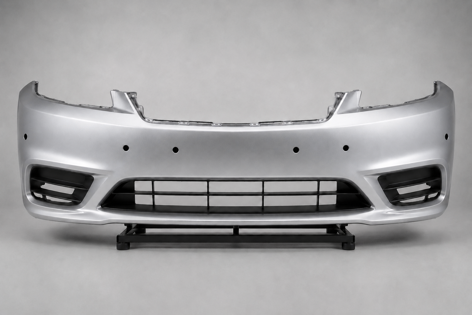
6 Radar Holes
|
Configuration |
DZ-1500SR |
DZ-1500DR |
|
Robot arrangement |
Single processing robot |
Dual processing robots |
|
Laser arrangement |
1 x 1500 W laser source |
2 x 1500 W laser sources |
|
Reference use case |
Four-hole bumper programs; moderate takt time |
Six-hole or higher-output programs; parallel processing |
|
Reference cycle |
Approximately 20 s for four radar holes |
Approximately 15 s for six radar holes |
|
Strength |
Lower investment and simpler cell layout |
Higher throughput and reduced robot-travel bottlenecks |
|
Selection basis |
Hole count, contour, weld count, robot access, takt time, budget |
Higher volume, more holes, parallel work, future capacity |
The correct selection must be based on the complete cycle, not only nominal laser cutting time. Dizo Sonics uses layout planning, robot reach checks, offline simulation, and sample trials to establish the project configuration.
|
Parameter |
Reference Specification |
Engineering Note |
|
Machine models |
DZ-1500SR / DZ-1500DR |
Single-robot / dual-robot |
|
Primary process |
Robotic laser cutting + ultrasonic bracket welding |
One coordinated cell |
|
Laser power |
1500 W per cutting robot |
IPG reference; equivalent brands by project |
|
Laser cutting time |
Approx. 2 s for a 30 mm circular hole |
Contour-only reference; excludes robot travel |
|
Robot brands/models |
ABB IRB 4600 series reference |
Final payload/reach selected by layout |
|
Front-bumper robot reference |
ABB IRB 4600-40/2.55 |
Project-specific selection |
|
Rear-bumper robot reference |
ABB IRB 4600-60/2.05 |
Project-specific selection |
|
Ultrasonic system |
35 kHz, 1200 W per unit reference |
Quantity defined by weld-point strategy |
|
Ultrasonic brand |
Sonotronic reference |
Customer-approved equivalent optional |
|
PLC / HMI |
Siemens |
Recipe, alarms, diagnostics, manual/auto modes |
|
Standard power |
380 V, 50 Hz, 3-phase |
Adaptable to destination plant requirements |
|
Fixture changeover |
15-20 min reference |
Electric forklift and standardized connections |
|
Data interface |
Local recipe and production data |
MES interface optional; protocol defined by project |
|
Safety |
Guarded laser area, interlocks, emergency stops, safety sensors |
Final design per destination requirements |
|
Fume management |
Local extraction at cutting area |
Airflow and filtration defined by actual material and coating |
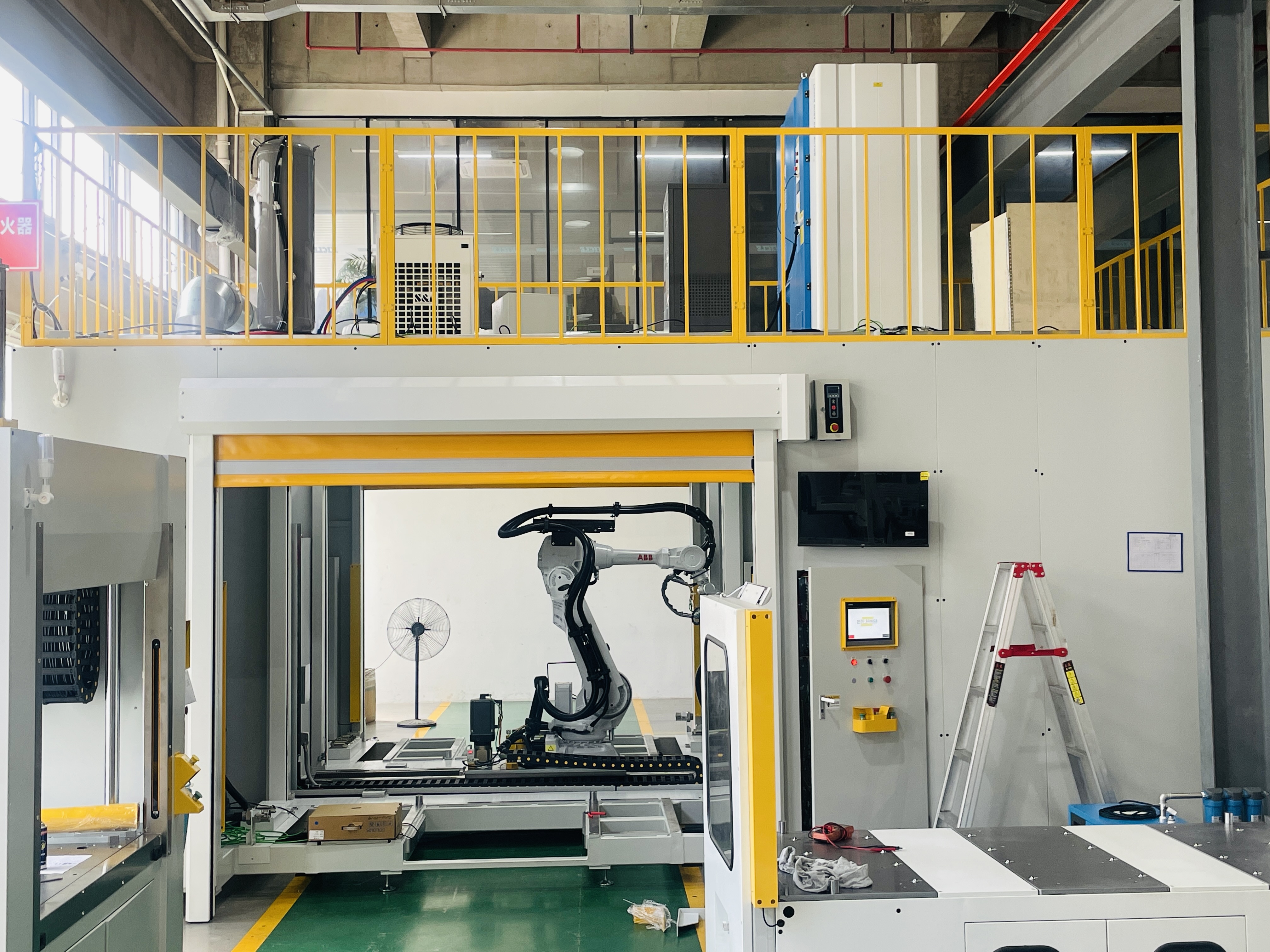
|
REFERENCE SPECIFICATIONS: Final parameters are confirmed after drawing review, layout planning, simulation, and sample trials. |
Automotive bumpers commonly use PP-based compounds such as PP/EPDM or TPO, while brackets and related components may use PP, ABS, PC/ABS, or other engineering thermoplastics. Material names alone are not enough to approve the process. Fillers, pigments, paint systems, wall thickness, joint design, and production history can change cutting and welding behavior.
Dizo Sonics therefore evaluates the complete application through resin and coating review, drawing analysis, laser-cutting trials, ultrasonic joint trials, visible-surface inspection, and mechanical testing. Painted Class A parts require special attention to heat input, fumes, edge condition, support, weld amplitude, force, and horn contact.
|
MATERIAL VALIDATION: Compatibility is confirmed using the customer's actual parts, material data, paint system, joint design, and quality standard. |
A production-ready cell should be accepted against measurable requirements agreed before manufacture. Typical checks include:
|
Decision Factor |
Robotic Laser Cutting |
Mechanical Punching |
|
Hole geometry |
Program-controlled; supports multiple shapes after validation |
Defined by punch and die geometry |
|
Product variants |
Strong flexibility through recipes and fixtures |
Additional dedicated tooling commonly required |
|
Engineering changes |
Program, validation, and possibly fixture changes |
Punch/die modification or replacement |
|
Tool wear |
No conventional cutting-edge wear; optics and focus require control |
Punch/die inspection, sharpening, and alignment required |
|
Cycle time |
Depends on contour, travel, extraction, and hole count |
Often very fast for one fixed geometry |
|
Edge/process risk |
Heat input, fumes, paint response, focus, and robot path |
Burrs, stress, deformation, tool wear, and alignment |
|
Best fit |
Mixed models, special shapes, engineering changes, flexible lines |
Stable high-volume programs with limited variants |
|
Investment decision |
Evaluate lifetime program flexibility and capacity |
Evaluate tooling quantity, maintenance, and changeover |
Laser cutting is not automatically better for every project. Dizo Sonics recommends the process that produces the required quality and takt time at the best total cost across the vehicle program.
Read our engineering comparison: Laser Cutting vs. Mechanical Punching for Bumper Sensor Holes.
The fixture is central to both cut quality and ultrasonic weld quality. It must locate the bumper repeatably, protect the Class A surface, support the cutting and welding zones, provide robot access, control deformation, and release the part without damage.
For multiple bumper variants, Dizo Sonics can use standardized fixture bases, coded connections, recipe control, and planned change parts. A reference fixture changeover of 15-20 minutes may be achievable with an electric forklift. The final method and time are confirmed against the approved fixture design, weight, access, and validation procedure.
The Siemens PLC and HMI coordinate robot programs, laser commands, ultrasonic recipes, fixtures, safety, alarms, and operating modes. The standard system should present clear diagnostics, controlled manual functions, maintenance access, recipe authorization, and production counters.
Where required, optional integration can exchange model, start, result, fault, and production data with upstream/downstream equipment or the plant system. The final interface, protocol, tag list, data retention, cybersecurity requirements, and MES responsibility must be defined during project engineering.
The cell design should combine laser guarding, access interlocks, emergency stops, safety sensors, controlled robot operating modes, extraction monitoring, electrical protection, and documented recovery procedures. Final safety architecture must match the installation country, laser class, customer standard, risk assessment, and agreed scope.
Laser cutting of painted polymers can generate fumes and particles. The extraction and filtration system is selected for the actual material and coating. Applicable airflow, filter type, noise, emissions, and maintenance intervals are confirmed during project engineering.
Review 3D models, drawings, resin/coating information, samples, quality requirements, takt time, model mix, and plant interfaces.
Develop the process sequence, cell layout, robot reach, tooling concept, safety concept, preliminary takt-time model, and interface list.
Validate cutting edge, visible-surface response, bracket joint design, ultrasonic process window, and agreed mechanical tests.
Release mechanical, electrical, software, robot, laser, ultrasonic, fixture, extraction, and documentation work after technical approval.
Complete internal testing, FAT, customer sample production, punch-list closure, packing, installation, SAT, and training according to contract.
Provide manuals, maintenance guidance, spare-parts recommendations, remote support, and optional on-site service according to project scope.
Reference tooling lead time is approximately 45 days, and the reference lead time for a complete dedicated machine is approximately 90 days. The final project schedule is confirmed after technical scope approval.
Established in 2007, Dizo Sonics focuses on plastic joining equipment and application-specific automation. For bumper projects, one engineering team coordinates the fixture, robot path, laser cutting, extraction, ultrasonic welding, controls, safety, and acceptance requirements as a complete production system.
Send the following information so the engineering team can evaluate feasibility, configuration, and cycle time:
This cell uses the laser to cut bumper openings and uses ultrasonic energy to join plastic brackets. The laser does not create the bracket joint. Calling it a laser welding machine alone would be technically inaccurate.
Potentially, yes. The feasibility depends on robot reach, cell layout, fixture strategy, bumper size, model matrix, hole positions, and takt time. Separate fixtures and recipes are normally required.
Yes, programmable robot paths can produce round, oval, rectangular, and special contours. Every new geometry must still be validated for dimensional accuracy, edge quality, heat input, coating response, and cycle time.
Painted parts can be processed only after trials confirm acceptable edge condition, fumes, heat response, color/finish, and Class A appearance. The laser source, optics, focus, speed, extraction, and material/coating must be evaluated together.
The process uses dedicated support, controlled clamping, validated horn geometry, and a defined weld window. Amplitude, force, energy/time, hold, wall thickness, and bracket joint design must be optimized using actual parts.
Choose based on complete takt time, hole and weld count, robot access, variant mix, capacity, floor space, budget, and future programs. A dual-robot cell is not automatically necessary if one robot can meet the validated cycle.
Include loading, identification, clamping, robot travel, cutting, extraction delay, bracket loading, ultrasonic welding, inspection, data exchange, unclamping, and unloading. Simulation and sample trials provide a more reliable result than adding nominal laser and weld times only.
No. Mechanical punching can be the most economical process for one stable high-volume geometry. Laser cutting becomes more attractive when variants, special contours, engineering changes, and reduced dedicated-tooling requirements are important.
PP-based bumper compounds are common, and brackets may use PP, ABS, PC/ABS, or other thermoplastics. Compatibility depends on the actual resin, fillers, pigments, coating, wall thickness, joint design, and process trials.
A reference changeover of 15-20 minutes may be achievable with standardized connections and an electric forklift. The final method and time must be confirmed using the approved fixture design, weight, access, and validation procedure.
Options include part/model verification, hole presence and dimensions, bracket presence/orientation, ultrasonic process monitoring, vision inspection, barcode/RFID, mechanical sample testing, and production data logging. The final inspection plan must match the customer's control plan.
Yes, an interface can be engineered for model, start, result, fault, and traceability data. Protocol, tag list, database ownership, cybersecurity, data retention, and commissioning responsibilities must be agreed in scope.
The project package can include layout, electrical/pneumatic documentation, operation and maintenance manuals, spare-parts list, parameter guidance, FAT/SAT records, and operator/maintenance training according to contract.
Send 3D files, 2D drawings, material/coating data, samples, hole and bracket details, model matrix, target cycle time, annual volume, quality standard, plant interfaces, and preferred component standards.
Send your bumper and bracket files, material/coating information, hole and weld drawings, model matrix, target cycle time, annual volume, and plant requirements. Dizo Sonics will review the application and recommend a single-robot, dual-robot, laser, punching, or combined solution based on the complete production requirement.


