Select a bumper PDC bracket ultrasonic welding machine from the joint, weld map, fixture and complete station cycle. Parking sensor bracket welding must preserve bracket retention, sensor alignment and the painted Class A surface. Compare robotic ultrasonic welding with fixed multihead ultrasonic welding after confirming that the actual bumper and bracket can be joined.
Record the exact bumper and bracket resin grades, fillers, coatings and permitted recycled content. A PP bumper or TPO bumper requires grade-specific review. Compatible thermoplastics and suitable contact geometry are essential to a fusion weld; material names alone do not approve the application.
This guide considers ultrasonic spot welding at bracket mounting feet using a slim piercing horn. Herrmann distinguishes spot welding from staking: staking reshapes a plastic post to retain another component. Confirm the joint type on the drawing because the horn, penetration or forming depth and acceptance features differ.
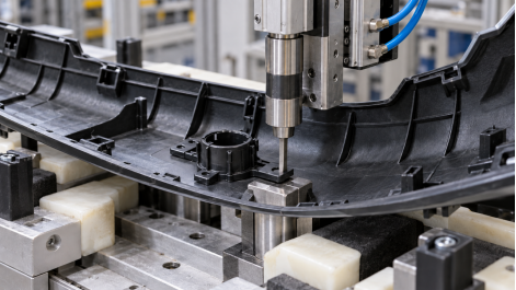
AI-generated application illustration of a pneumatic ultrasonic module and small flat piercing horn at a bracket foot. Tooling geometry requires validation.
Give each weld point an identity, approach direction and bracket reference. Check clearance to the sensor holder, ribs and nearby features. A pneumatic ultrasonic welding module needs a controlled approach and a stable force path through the local joint. Its cylinder positions and loads the acoustic stack; the horn remains a nonrotating ultrasonic tool.
The bumper welding fixture should locate the fascia and support each bracket foot from beneath without damaging the visible surface. Herrmann's fixture guidance explains that fixture material affects support and energy transfer. Check seating, contamination and pad wear with production parts before changing the ultrasonic generator settings.
Use a welding process window trial to compare nominal and nearby settings on representative assemblies. Include molded cavity variation and permitted paint or material changes. Evaluate weld force repeatability, horn alignment and first parts after changeover using the same retention and appearance methods. Select the head firing sequence after testing the actual bumper and fixture. Preserve individual weld records so that the performance of one weak attachment remains visible.
|
Selection factor |
Robotic concept |
Fixed multihead concept |
|
Weld access |
Moves the tool between accessible distributed points. |
Each head needs mounting space and a suitable approach. |
|
Variant changes |
Review paths, end tooling and fixture changes. |
Review head positions, tooling changes and recipe selection. |
|
Capacity study |
Include travel, contact and joining at every point. |
Validate grouped firing, support and head interaction. |
A robot provides path flexibility within its proven reach and tool-access envelope. Fixed heads may process points in groups, subject to trials. Verify acoustic interaction and available power before assuming simultaneous operation. Tooling changeover, loading, clamping and inspection contribute to output in both layouts.
Define bracket retention tests with the required load direction, conditioning and permitted failure modes. Check sensor-hole location, bracket position and sensor axis against the approved datums. A strong weld can still place the sensor incorrectly. Use the specified checking fixture or measurement method to assess the released assembly.
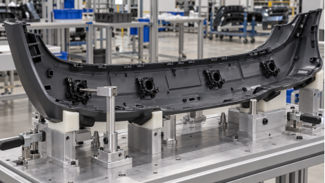
AI-generated application illustration of PDC bracket position inspection. The reference gauge is conceptual and shows no measured result.
Inspect the Class A surface under agreed lighting and viewing conditions. Record dents, gloss changes and distortion separately. Compare incoming parts with clamped parts and completed assemblies when tracing a mark. Repeat retention and dimensional checks after a horn, fixture or recipe correction.
Specify bracket presence, variant verification, weld monitoring and reject handling. Record available results by weld point and recipe revision. Data export and MES connectivity require an explicit scope. During acceptance, challenge missing components, wrong variants and interrupted cycles using the agreed recovery procedure.
Compare the full station cycle, including loading, tool movement, welding, hold, inspection and unloading. No universal seconds-per-point value establishes line capacity. Where hole production is also required, our bumper hole cutting and bracket assembly guide addresses the combined process.
Dizo Sonics offers robotic ultrasonic welding workstations and custom multihead ultrasonic systems. The bumper layout and tooling need an application review. Send fascia and bracket CAD, the weld map, exact materials, paint specification, production samples, retention and appearance limits, sensor-position criteria, variant mix and target cycle.
Contact Dizo Sonics with these requirements to compare a bumper welding machine concept and define the trials needed before a firm equipment specification.


