One linear vibration welding machine can serve several plastic part variants when every part and its tooling fit the same qualified machine capability. Check the upper moving mass, joint design, clamping requirements and loading sequence for each variant. Then validate its weld recipe and the procedure for changing tools. The number of products alone does not establish whether a shared machine is suitable.
For automotive and industrial purchasing teams, a small housing with heavy tooling may be more demanding than a larger, lighter assembly. Review the complete product family before selecting a machine.
Linear vibration welding generates frictional heat by moving one plastic component back and forth against the other under load. Motion stops and force is maintained while the joint cools, as described in TWI's process explanation. The assembly needs a joint that accommodates this movement and controlled final alignment.
Large thermoplastic housings and duct assemblies are candidates when the seam is accessible to suitable tooling. Review the complete seam, nearby features and flash requirements. If the geometry cannot accommodate the motion, compare another joining method during feasibility review. Our hot plate welding guide explains an alternative based on an external heated tool.
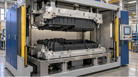
AI-generated application illustration of an idle linear vibration welding setup with matched upper and lower tools holding plastic housing halves.
Create one row per variant in the project data sheet and compare the following fields. Include proposed future variants if they are part of the purchase decision. This is a recommended selection framework; machine limits and acceptance criteria must come from the agreed equipment specification.
|
For each variant |
Information to compare |
Selection question |
|
Part envelope |
Both halves, datums, loading height and removal path. |
Do parts and tooling fit throughout the sequence? |
|
Upper moving assembly |
Tool and part mass, attachments, mass distribution and mounting. |
Is this assembly approved for the vibration head? |
|
Lower assembly |
Fixture mass and height, services and lift travel. |
Can the table carry, close and open this setup? |
|
Weld interface |
Joint section, weld area, motion clearance and flash space. |
Can the seam be heated, clamped and aligned? |
|
Material condition |
Exact grades, fillers, moisture and permitted variation. |
Which combinations need separate trials? |
|
Production demand |
Variant mix, batch size, station cycle and inspection. |
Does usable capacity cover the production plan? |
Ask the supplier to identify the limiting variant for each requirement. The longest part may define platen length, while another defines the upper mass limit or required clamping force. Also check the lightest upper assembly against the approved operating range. One successful demonstration cannot establish that the full family fits.
Specify the exact resin grade for both halves, including reinforcement, additives and permitted recycled content. Record the relevant moisture or conditioning requirements. A polymer family name such as PP or PA does not establish that two production grades will weld satisfactorily. Use representative molded parts to investigate uncertain combinations.
Review joint cross-sections along the entire seam. Check the contact land, local wall stiffness, flash accommodation and clearance during oscillation. TWI's friction-welding guidance explains that wall flexing can reduce the relative motion needed at the interface. Inspect how the proposed nest supports the walls and transfers motion into the joint.
If trials show uneven fusion, compare part seating, dimensional variation and local support before increasing the process input. Retain sections or failed samples from the affected locations. A tooling change or joint revision may be necessary. Increasing machine size alone does not resolve an unsuitable seam design.
Obtain a mass estimate for each complete moving upper assembly. Agree whether the quoted allowance includes the part, baseplate, clamps, adapters and other attachments. Record the lower fixture separately because it loads a different machine assembly. A single combined tooling weight can hide which limit is being approached.
Ask the machine supplier to review mounting geometry, mass distribution, rigidity and the permitted vibration frequency and amplitude with each tool. Published vibration-welder specifications treat upper tool weight and head operating conditions as distinct selection inputs. Their model values belong to that manufacturer and should not be transferred to another platform.
Confirm the amplitude convention, including whether a value means peak-to-peak displacement. Define required joint force and how the machine reports or derives it; a supply-pressure reading requires a known relationship to delivered force. Check the lift travel and available opening with the actual tool stack installed. These definitions make competing quotations easier to compare.
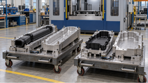
AI-generated application illustration of matched tool sets in storage. Tool supports, handling equipment and mounting interfaces require project-specific engineering.
Upper and lower tools form a matched set with defined part datums. Vibration welding tooling guidance describes the role of the fixtures in supporting and aligning the assembly. Give each tool pair a controlled identity and record the corresponding part and recipe revisions.
Specify the required verification method. Mechanical identification, operator confirmation or automatic tool recognition may be appropriate depending on the project. Where automatic recognition is included, define the response to a mismatched tool or recipe. Recipe storage alone does not verify that the correct physical tooling is installed.
Measure changeover from the last accepted part of one variant to the first approved part of the next. Include tool transport, securing both tools, reconnecting services, setup checks and first-part inspection in the production interruption.
Follow the supplier's approved isolation and handling procedure. Verify locating surfaces, tool retention, service connections and clearances. Complete required tuning or setup checks and first-part inspection before release. Specify tool carts, lifting aids, connectors and storage arrangements in the quotation.
Agree the factory acceptance test, or FAT, before the build. We recommend covering the heaviest and lightest approved upper assemblies, the most demanding seam and the tightest dimensional or appearance requirement. These conditions may occur on different variants.
Connect each recipe and available cycle records to physical results. Check strength, dimensions, flash and specified leak, burst or functional performance using the customer's methods and conditioning requirements. Process records support monitoring; physical tests establish whether the assembly meets its requirements.
Demonstrate a change away from and back to a qualified variant. Compare first approved parts with the previous run and challenge tool and recipe checks where supplied. Record the complete station cycle. Family qualification needs an agreed technical rationale and documented coverage.
Compare production mix and batch sizes with machine hours available after changeovers, inspections and maintenance. A dedicated station may suit a sustained high-volume variant; a shared platform may suit compatible parts with manageable batch changes. Include future tooling cost, storage and the effect of a machine being unavailable.
Dizo Sonics supplies linear vibration welding systems for large thermoplastic parts, with platform and tooling selection based on the application. Tool identification, handling aids, inspection interfaces and data connectivity must be confirmed in the project scope. To begin a review, send:
Contact Dizo Sonics with the complete family so the proposal can identify which variants share a platform, which need trials, and which require a different process or machine configuration.


