

Custom pneumatic ultrasonic welding equipment for attaching brackets and clip carriers to automotive wheel arch trim. Dizo Sonics develops the tooling and station layout around your part geometry, joint design and production requirements.
Send your wheel arch assembly CAD, exact resin grades and weld-point drawing for an application review and project quotation.
Request a Wheel Arch Welding Proposal
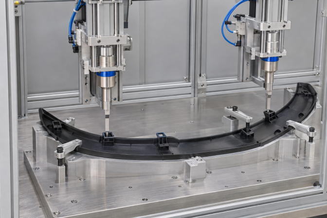
AI application illustration. Generic wheel arch trim fixture and pneumatic ultrasonic modules with slender flat piercing sonotrodes. This is not a customer machine photograph or an approved tooling design.
A wheel arch ultrasonic welding machine joins local attachment features on a molded exterior trim assembly before the finished part is fitted to the vehicle. The application can include mounting brackets, clip carriers and inner supports, provided the materials and joint geometry are suitable for ultrasonic joining.
The machine concept described here uses pneumatic cylinder-driven ultrasonic modules. A dedicated fixture locates the curved trim and supports the working area, while individually positioned tools approach the specified joining points. For a suitable piercing spot-weld joint, a slender, flat piercing sonotrode provides access to a restricted bracket area. Horn geometry and penetration are established through application trials.
This wheel arch trim welding machine is intended for component assembly. The tooling must be reviewed separately for each front, rear, left-hand or right-hand part; a common vehicle program does not automatically make every variant compatible with the same fixture.
|
Assembly feature |
Joining task |
What to review before equipment selection |
|
Mounting bracket |
Attach a bracket to the inner face of the trim |
Material compatibility, overlap and required load direction |
|
Clip carrier |
Secure the carrier that receives a vehicle mounting clip |
Carrier location, clip insertion clearance and retention test |
|
Local inner support |
Connect a support at specified joining points |
Available support beneath the joint and tool access |
|
Fender flare trim assembly |
Join attachment features on a molded flare where the design permits |
Exact construction, visible-surface requirements and installation fit |
Wheel arch trim, fender flares and wheel-house liners describe different component constructions. Share the actual assembly drawing so that the proposal addresses your part and its attachment function.
The pneumatic cylinder advances and retracts the guided welding unit and applies the required joining load. The ultrasonic generator and acoustic stack produce the high-frequency vibration delivered through the sonotrode. These functions are evaluated separately during setup: the air-pressure setting alone does not establish the force delivered at the joint.
For the piercing configuration, the working end is a slender, flat ultrasonic horn. Its access path must clear nearby ribs, clip features and clamp fingers throughout approach, welding and retraction. A narrow tip does not remove the need to check the clearance of the complete acoustic stack.
The final horn must suit the acoustic system and joint. Where the drawing calls for a molded post to be formed into a retaining head, that point requires ultrasonic staking tooling. A piercing spot-weld joint and a formed stake have different mechanisms and acceptance criteria. They are identified separately on the weld map and in the quotation.
The fixture should react the welding load close to the working area. When a curved trim section bends under the tool, the measured movement can include component deflection. This can make the same machine setting produce different results on parts with different initial gaps or curvature.
During concept review, identify the reaction surface beneath each bracket and confirm that the support can be installed without obstructing loading. A preliminary check should also confirm whether the bracket seats naturally before clamping. If a clamp has to pull a substantial gap closed, review the part fit before approving the joining concept.
For painted, textured or high-gloss wheel arch trim, specify the visible inspection zones and approved appearance samples. Fixture contact areas and local supports must be assessed with representative production parts. A soft contact pad alone does not establish that the fixture will prevent marks or read-through.
Appearance checks should distinguish marks already present on the molded part from those introduced during clamping or welding. This gives the trial team a practical way to decide whether to change a contact surface, local support, tool position or process setting.
Provide the complete variant list when discussing tooling. Dedicated fixtures or an agreed quick-change arrangement can be considered after checking the common machine envelope. Fixture identification and recipe verification can be specified to help control changeover.
The head sequence follows the weld map. Any proposed simultaneous firing must be checked for its effect on part movement, fixture loading and appearance. Total station cycle time includes loading, checks, clamping, joining, hold stages and unloading.
The following table defines the main items to agree for a custom wheel arch ultrasonic welding machine. The quotation and approved specification establish the supplied configuration.
|
Item |
Configuration basis |
|
Component |
Automotive wheel arch trim with defined brackets, clip carriers or local supports |
|
Actuation |
Pneumatic cylinder-driven guided ultrasonic modules for the proposed configuration |
|
Joining method |
Piercing spot welding or another validated ultrasonic joint; staking identified separately |
|
Sonotrode |
Slender, flat piercing horn where suitable; final geometry by acoustic design and trials |
|
Head quantity and orientation |
Determined from the complete weld map and access study |
|
Fixture |
Dedicated contoured nest with defined datums, local supports and clamps |
|
Frequency and generator power |
Selected for the joint and tuned acoustic tooling |
|
Weld control |
Available modes and result fields confirmed for the selected generator and controller |
|
Loading and changeover |
Defined from part handling, variant mix and target output |
|
Utilities and machine envelope |
Confirmed from the final layout and destination plant requirements |
|
Production cycle |
Established from trials and the complete station sequence |
Provide the exact grades for both the wheel arch trim and the attachment component. PP-based compounds, TPO, ABS and other thermoplastics require grade-specific assessment. Fillers, modifiers, recycled content, coatings and molded-part condition can influence the joining process.
For a fusion weld, confirm that the mating materials and interface can form the required bond. For a mechanically retained stake, check the molded post and retained component instead. A generic description such as “plastic wheel arch” is insufficient to approve either process.
Where feasibility is uncertain, representative molded parts and a defined test method allow the trial to answer a specific question: whether the proposed joint meets its retention, dimensional and appearance requirements.
Project options can include bracket-presence checks, fixture identification, controlled recipe selection, vision inspection and storage of available weld results. Each function should be tied to a defined production requirement. For example, bracket detection addresses a missing component; a location gauge addresses an incorrectly positioned carrier.
Specify whether records are required for each joining point, firing group or finished assembly. The available data depend on the generator, controller and sensors included in the machine. Weld energy or time alone does not demonstrate the final retention strength. Network communication and MES interfaces are separately agreed project items.
If changing weld positions or a varied product mix favors robot access, compare the fixed-module concept with the Robotic Ultrasonic Welding Workstation. The choice should follow the access study, required output and changeover plan.
Before machine acceptance, agree how the wheel arch assembly will be evaluated. Relevant checks can include bracket retention in the specified loading direction, clip-carrier location, visible-surface appearance and fit to the installation gauge. Identify any conditioning or durability tests required by the customer specification.
Use representative variants and record the material, tooling identity and process settings for tested samples. Acceptance criteria should also cover an interrupted cycle and the permitted recovery method. This prevents an undefined restart from becoming a production workaround.
FAT and SAT scope, sample quantities, test fixtures and responsibility for supplying parts are established in the project plan.
A shared station can be assessed when the parts fit the available head and fixture envelope. Send both variants, their weld maps and the required changeover time. The tooling proposal should identify which nests, references and programs change between parts.
The firing strategy requires a trial-supported review. A multihead arrangement may use several groups when access, generator capacity or part movement makes a single simultaneous operation unsuitable. Head quantity by itself does not define the production cycle.
In piercing spot welding, penetration is part of forming the local joint. If the wheel arch assembly also needs a separately dimensioned mounting hole or cutout, specify that feature and its tolerance as an additional operation.
The quotation depends on the joining-point layout, tooling complexity, variant quantity, handling method, inspection functions and required project documentation. Part data and acceptance requirements allow the proposal to define these items clearly.
Send Dizo Sonics the following information to start the technical review:
Contact Dizo Sonics with your wheel arch trim project details. We will review the proposed joint, tooling access and machine scope for a technical quotation.
For process terminology, see Sonics technical guidance on ultrasonic staking and spot welding. For fixture principles, see Herrmann guidance on ultrasonic welding fixtures. These references describe general process principles; they do not define the equipment supplied for a Dizo Sonics project.


